


MAN0443.P65 Issue 13 Aug 04
5701 Control System
05701-M-5001 A02279
CHAPTER 4 - INSTALLATION INSTRUCTIONS
4 - 55
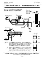
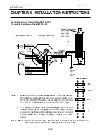
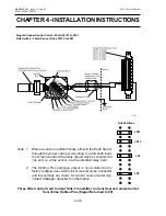
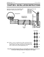
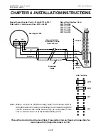
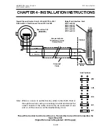
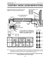
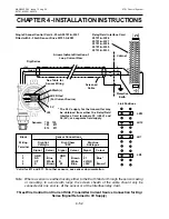
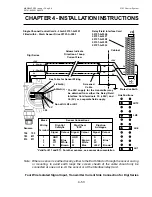
Four Wire Floating Signal Input, Transmitter Current Source Connection
NS
Screened
Cable
Cabinet
Protective
Earth
+24V
0V
Arrows Indicate Direction of
Loop Current Flow
Link Positions
LK12
LK10
LK7
Relay/Field Interface Card
05701-A-0326
05701-A-0327
05701-A-0328
05701-A-0329
05701-A-0330
Single Channel Control Card 4 - 20mA 05701-A-0301
Fitted with 4 - 20mA Sensor Drive 05701-A-0283
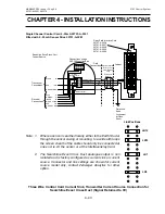
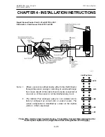
28
29
+24V*
+4 - 20mA
-4 - 20mA
0V*
GND
+
-
Earth Stud
36
35
01
* The 24V supply for the transmitter may be
obtained from either the Relay/Field Interface
Card terminals 35 (+24V) and 36 (0V), or a
separate field supply.
Содержание 5701
Страница 1: ...Sieger System 57 5701 Control System Operating Instructions ...
Страница 45: ...2 32 MAN0443 P65 Issue 13 Aug 04 5701 Control System 05701 M 5001 A02279 CHAPTER 2 SYSTEM DESCRIPTION ...
Страница 63: ...3 18 CHAPTER 3 CONTROLS AND FACILITIES MAN0443 P65 Issue 13 Aug 04 5701 Control System 05701 M 5001 A02279 ...
Страница 139: ...4 76 MAN0443 P65 Issue 13 Aug 04 5701 Control System 05701 M 5001 A02279 CHAPTER 4 INSTALLATION INSTRUCTIONS ...
Страница 173: ...6 12 MAN0443 P65 Issue 13 Aug 04 5701 Control System 05701 M 5001 A02279 CHAPTER 6 OPERATING INSTRUCTIONS ...
Страница 209: ...9 4 MAN0443 P65 Issue 13 Aug 04 5701 Control System 05701 M 5001 A02279 CHAPTER 9 ORDERING INFORMATION ...


