Chapter 3 Exterior Views
3 - 2
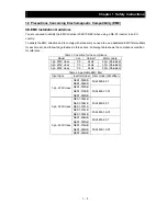
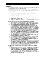
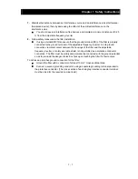
3.2 Name of each portion (removing the front cover)
Note1)
Name Description
1) Connector of dedicated operator for
NES1-OP
Dedicated operator for NE-S1 (NES1-OP) can be connected.
2) RUN/STOP/RESET key
Push key for run, stop and reset operation.
3) Intelligent relay terminal
Output terminal for intelligent relay (1c contact).
4) Main terminal
For connecting power supply, motor output and DC reactor.
5) Switch for termination resistor
Changeover for integrated resistor (100
Ω
) for RS485.Integrated resistor of 100
Ω
is
connected when turning ON.
6) Switch for RS485/OPE
Changeover switch for RS422/RS485.
7) RS422/RS485 port
Connector for RS485 or external operator and PC software (RJ45 jack)
8) Switch for O/OI (analog input)
changeover
Voltage input (O) or current input (OI) can be selected.
9) Logic terminal A,B
Terminal for connecting input/output signals (digital/analog) for the inverter control.
10) Charge lamp
Turns ON when the internal DC bus voltage is 45V or more.
In case of wiring, maintenance or else, be sure to check that this lamp is turned OFF after
waiting 10 minutes of power OFF.
Note 1) Refer to section 6.5 How To Operate the Inverter.
Note 2) Position of “10) charge lamp” depends on the model. Refer to page 2-11 for the details.
Note 3) Pay attention when operating by PC via “7)RS422/RS485 port”, because the operation can also be done from the
panel of the inverter.
Note 4) Be sure to turn power OFF when connecting or disconnecting the operator such as OPE-SRmini,OPE-S,WOP to the
“7) RS422/RS485 port”.
Note 5) When communication becomes unstable, Please do not use the termination resistor of the inverter. Please use a
termination resistor suitable for your environment.
6) Switch for RS485/OPE SW5
5) Switch for termination resistor SW4 Note5)
7) RS422/RS485 port Note3) Note4)
2) RUN/STOP/RESET key
4) Main terminal
9) Logic terminal A
section 5.4
8) Switch for O/OI (analog input)
changeover SW6
9) Logic terminal B
3) Intelligent relay terminal
10) Charge lamp Note2)
1) Connector of dedicated
operator for NES1-OP
section 5.4
OFF
(Default)
ON
section 5.4, 8.3
RS485
OPE
(Default)
→
section 5.4, 8.3
Voltage O
(Default)
Current OI
section 5.4
section 5.5
Содержание NES1-002LB
Страница 9: ......
Страница 21: ......
Страница 25: ......
Страница 28: ...Chapter 3 Exterior Views 3 3 ...
Страница 29: ...Chapter 4 Installation This chapter describes how to install the inverter 4 1 Precautions for installation 4 1 ...
Страница 30: ......
Страница 35: ......
Страница 53: ......
Страница 75: ......
Страница 154: ......
Страница 196: ......
Страница 203: ...Chapter 10 Troubleshooting This chapter describes the troubleshooting methods ...
Страница 204: ......
Страница 211: ......
Страница 219: ......
Страница 229: ......
Страница 289: ...Appendix Appendix A Appendix A 1 ...
Страница 290: ......
Страница 292: ...Appendix Appendix 2 ...


