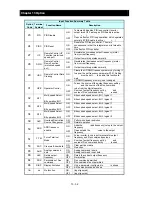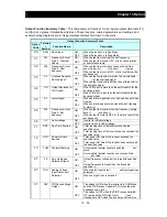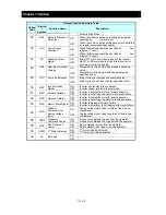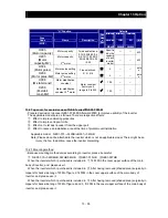
Index
Index - 3
RUN / STOP / RESET key .................................. 6-4
run command source setting ............................... 7-7
run command LED .............................................. 6-5
Run Mode Edit .................................................. 7-45
RV ....................................................................... 7-7
RVR .................................................................. 7-74
S
S-curve acceleration / deceleration ................... 7-30
scaled output frequency monitoring .................... 7-2
2nd control ........................................................ 7-40
SET ................................................................... 7-40
SETM ................................................................ 7-76
SET key .............................................................. 6-5
SFT ................................................................... 7-45
SF1, SF2, SF3 .................................................. 7-28
side-by-side ........................................................ 4-3
sink logic ........................................................... 5-13
software lock ..................................................... 7-45
source logic ....................................................... 5-13
specifications .................................................... 12-1
STA ................................................................... 7-23
stabilization constant ......................................... 7-39
start/end frequency setting for external
analog input ................................................. 7-18
start frequency .................................................. 7-18
start-frequency rate ........................................... 7-18
starting contact signal ....................................... 7-72
stop mode selection ............................................ 7-8
STP ................................................................... 7-23
switch for termination resistor ............................. 3-2
T
termination resistors ............................................ 8-2
Thermal warning ............................................... 7-62
THM .................................................................. 7-62
tightening torque ............................................... 5-12
3-wire interface operation function .................... 7-23
torque boost ...................................................... 7-22
trip ..........................................................
6-19, 7-60
trip counter .......................................................... 7-4
trip monitoring ..................................................... 7-4
troubleshooting ................................................. 10-1
2-stage acceleration/deceleration ..................... 7-29
2CH ................................................................... 7-29
U
U-curve acceleration / deceleration ................... 7-30
UDC .................................................................. 7-32
UL ..................................................................... 1-10
unattended start protection ............................... 7-57
UP ................................................................... 7-32
UP key ................................................................ 6-5
UP/DWN ........................................................... 7-32
USP .................................................................. 7-57
UV ..................................................................... 7-13
V
V/f characteristic curve ...................................... 7-20
V/f gain setting .................................................. 7-33
VC ................................................................... 7-20
VP 1.7
th
power ................................................. 7-20
W
warning display ................................................... 9-5
warning monitoring ............................................. 7-5
WC ................................................................... 7-75
window comparator .......................................... 7-75
wiring of control circuit terminal ........................ 5-12
withstand voltage test ....................................... 11-3
Z
0Hz detection signal ......................................... 7-70
ZS ..................................................................... 7-70
Содержание NES1-002LB
Страница 9: ......
Страница 21: ......
Страница 25: ......
Страница 28: ...Chapter 3 Exterior Views 3 3 ...
Страница 29: ...Chapter 4 Installation This chapter describes how to install the inverter 4 1 Precautions for installation 4 1 ...
Страница 30: ......
Страница 35: ......
Страница 53: ......
Страница 75: ......
Страница 154: ......
Страница 196: ......
Страница 203: ...Chapter 10 Troubleshooting This chapter describes the troubleshooting methods ...
Страница 204: ......
Страница 211: ......
Страница 219: ......
Страница 229: ......
Страница 289: ...Appendix Appendix A Appendix A 1 ...
Страница 290: ......
Страница 292: ...Appendix Appendix 2 ...

