


Chapter 4 Explanation of Functions
4 - 8
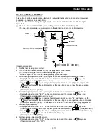
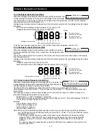
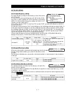
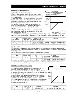
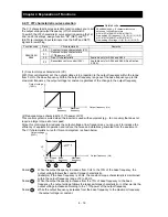
4.2.4 Frequency source setting
The frequency source setting function allows you to select the method to
input the frequency-setting command.
Motor rotation direction is inverted when -10 to 0V is given as frequency command to 02-L terminals.
Item Function
code
Data
Description
Frequency
source
setting
A001
(00)
(Valid only when the OPE-SR is used)
Use the control provided on the digital operator to set the frequency.
01
Input the frequency-setting command via a control circuit terminal (0-L,
OI-L, or O2-L).
02
Use the digital operator (function "F001") or remote operator to set the
frequency.
03
Input the frequency-setting command via an RS485 communication
terminal.
04
Input the frequency-setting command from the board connected to
optional port 1.
05
Input the frequency-setting command from the board connected to
optional port 2.
06
Use the SJ-FB to input the frequency-setting command as a pulse train
(see 4.2.21)
07
Use the SET-Freq command of the easy sequence function as the
frequency-setting command.
10
Use the operation result of the set frequency operation function as the
frequency-setting command. (see 4.2.12)
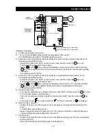
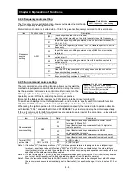
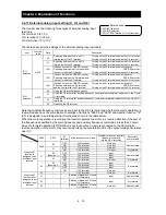
4.2.5 Run command source setting
The run command source setting function allows you to select the
method to input operation commands (to start and stop the motor).
As the operation commands via control circuit terminals, turn the
FW signal (for forward operation) or RV signal (for reverse
operation) on and off to start and stop the motor, respectively.
(Note that the factory setting assigns the FW signal to intelligent input terminal [8].)
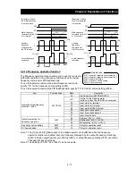
To switch each intelligent input terminal between a and b contacts, specify each terminal with function
"C011" to "C019", and then perform input a/b (NO/NC) selection for each terminal.
When using the digital operation for the inverter operation, specify the desired motor operation direction
with function "F004", and use the RUN and STOP/RESET keys to start and stop the motor, respectively.
If the start commands for both forward and reverse operations are input at the same time, the inverter will
assume the input of a stop command.
Item Function
code
Data
Description
Run command
source setting
A002
01
Input the start and stop commands via control circuit
terminals (FW and RV).
02
Input the start and stop commands from the digital or
remote operator.
03
Input the start and stop commands via RS485
communication terminals.
04
Input the start and stop commands from option board 1.
05
Input the start and stop commands from option board 2.
Terminal [FW]
active state
C019
C011 to C018
00
a (NO) contact
01
b (NC) contact
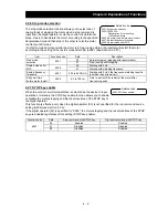
Note 1: If function "31" (forcible operation) or "51" (forcible-operation terminal) is assigned to an intelligent input
terminal, the settings made with functions "A001" and "A002" will be invalidated when the said intelligent
input terminal is turned on and those methods to input frequency-setting and operation commands which are
specified for the said terminal will be enabled.
Note 2: On the remote operator (SRW) being used to operate the inverter, pressing the REMT (remote) key enables
you to input both frequency-setting and operation commands from the remote operator.
Note3:
When the DeviceNet option board (SJ-DN) is used, A002 is not needed to be changed from default because
the run command source is automatically set via DeviceNet. (In case it is changed, it is to be set as 01, 02 or
03.)
A001: Frequency source setting
Related code
A002: Run command source setting
C001 to C008: Terminal [1] to [8] functions
C019: Terminal [FW] active state
F004: Keypad Run key routing
Related code
Содержание L700 Series
Страница 16: ... Memo ...
Страница 20: ... Memo ...
Страница 22: ... Memo ...
Страница 46: ... Memo ...
Страница 60: ... Memo ...
Страница 62: ... Memo ...
Страница 212: ... Memo ...
Страница 222: ... Memo ...
Страница 224: ... Memo ...
Страница 232: ... Memo ...
Страница 237: ...Chapter 7 Specifications 7 5 L700 300 LFF HFF L700 450 550 LFF HFF 750 HFF 5 Cable hole φ25 5 Cable hole φ41 ...
Страница 238: ...Chapter 7 Specifications 7 6 L700 750 LFF 6 Cable hole φ41 ...
Страница 239: ...Chapter 7 Specifications 7 7 L700 900 to 1100HFF L700 1320 to 1600HFF ...
Страница 240: ... Memo ...
Страница 242: ... Memo ...
Страница 258: ... Memo ...