


Chapter 4 Explanation of Functions
4 - 49
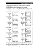
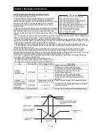
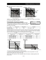
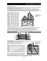
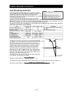
(1) Binary operation mode
Assign functions "02" (CF1) to "05" (CF4) individually to the terminal [1] to [8] functions (C001 to C008) to
make multispeed s 0 to 15 available for selection.
Specify the desired frequencies for speeds 1 to 15 by setting multispeeds 1 to 15 (A021 to A035).
You can set speed 0 by using function "A020", "A220", "A320", or "F001" (see Section 4.2.1) when you
have specified the digital operator for the frequency source setting. You can set speed 0 by using the O, OI,
or O2 terminal when you have specified the control circuit board for the frequency source setting.
Multispeed CF4 CF3 CF2 CF1
Speed
0 OFF OFF OFF OFF
Speed 1
OFF
OFF
OFF
ON
Speed
2 OFF OFF ON OFF
Speed 3
OFF
OFF
ON
ON
Speed 4
OFF
ON
OFF
OFF
Speed
5 OFF ON OFF ON
Speed 6
OFF
ON
ON
OFF
Speed 7
OFF
ON
ON
ON
Speed 8
ON
OFF
OFF
OFF
Speed 9
ON
OFF
OFF
ON
Speed
10 ON OFF ON OFF
Speed
11 ON OFF ON ON
Speed 12
ON
ON
OFF
OFF
Speed 13
ON
ON
OFF
ON
Speed 14
ON
ON
ON
OFF
Speed
15 ON ON ON ON
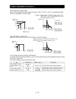
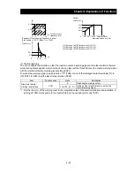
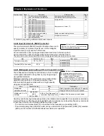
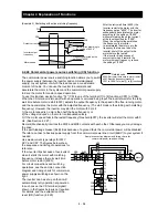
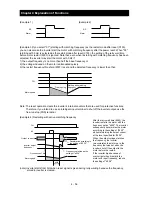
- With multispeed binary operation mode, you can use the multistage speed/position determination time
setting (C169) to specify a delay to be set until the relevant terminal input is determined. Use this
specification to prevent the application of fluctuating terminal input before it is determined.
- The input data is finally determined when terminal input becomes stable after the delay set as C169.
(Note that a long determination time deteriorates the input terminal response.)
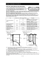
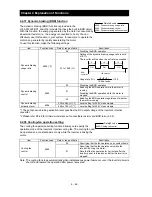
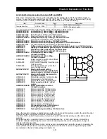
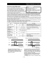
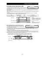
(2) Bit operation mode
- Assign functions "32" (SF1) to "38" (SF7) individually to the terminal [1] to [8] functions (C001 to C008) to
make multispeed s 0 to 7 available for selection.
- Specify the desired frequencies for speeds 1 to 7 (SF1 to SF7)
by setting multispeeds 1 to 7 (A021 to A027).
If two or more input terminals are turned on at the same
time, the terminal given the smallest terminal number
among them has priority over others. The "X" mark in the above table indicates that the speed can be
selected, regardless of whether or not the corresponding terminal is turned on.
Multispeed
SF7 SF6 SF5 SF4 SF3
SF2
SF1
Speed
0 OFF OFF OFF OFF OFF
OFF
OFF
Speed 1
×
×
×
×
×
×
ON
Speed 2
×
×
×
×
×
ON
OFF
Speed 3
×
×
×
×
ON
OFF
OFF
Speed 4
×
×
×
ON OFF
OFF
OFF
Speed 5
×
×
ON OFF
OFF
OFF
OFF
Speed 6
×
ON OFF
OFF
OFF
OFF
OFF
Speed
7 ON OFF OFF OFF OFF
OFF
OFF
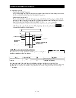
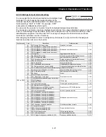
CF4
FW
CF3
CF2
CF1
Speed 1
Speed 2
Speed 3
Speed 4
Speed 5
Speed 6
Speed 7
Speed 8
Speed 9
Speed 10
Speed 11
Speed 12
Speed 13
Speed 14
Speed 15
Speed 0
Frequency input from
the digital operator or
via an external analog
input terminal
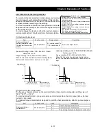
SF1
SF2
SF3
SF4
SF5
FW
SF6
SF7
Frequency input from
the digital operator or
via an external analog
input terminal
Speed 1
Speed 2
Speed 3
Speed 4
Speed 5
Speed 6
Speed 7
Speed 0
Speed 1
Determination time
CF1
CF2
CF3
Frequenc
13
1
5
9
Determination time (C169) = 0
11
CF4
15
Determination time (C169) specified
4
Содержание L700 Series
Страница 16: ... Memo ...
Страница 20: ... Memo ...
Страница 22: ... Memo ...
Страница 46: ... Memo ...
Страница 60: ... Memo ...
Страница 62: ... Memo ...
Страница 212: ... Memo ...
Страница 222: ... Memo ...
Страница 224: ... Memo ...
Страница 232: ... Memo ...
Страница 237: ...Chapter 7 Specifications 7 5 L700 300 LFF HFF L700 450 550 LFF HFF 750 HFF 5 Cable hole φ25 5 Cable hole φ41 ...
Страница 238: ...Chapter 7 Specifications 7 6 L700 750 LFF 6 Cable hole φ41 ...
Страница 239: ...Chapter 7 Specifications 7 7 L700 900 to 1100HFF L700 1320 to 1600HFF ...
Страница 240: ... Memo ...
Страница 242: ... Memo ...
Страница 258: ... Memo ...