


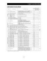

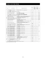
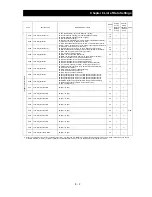


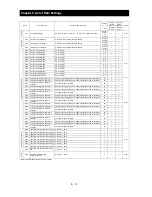
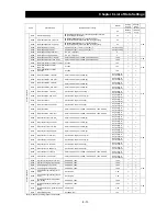
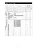


Chapter 8 List of Data Settings
8 - 5
Code
Function name
Monitored data or setting
Default
Setting
during
operation
(allowed
or not)
Change
during
operation
(allowed
or not)
Page
_FF
AV
R
A081
AVR function select
00 (always on), 01 (always off), 02 (off during deceleration)
02
¯
¯
4-11
A082
AVR voltage select
200 V class: 200, 215, 220, 230, 240 (V)
400 V class: 380, 400, 415, 440, 460, 480 (V)
200/400
¯
¯
Oper
ati
on m
ode
and
a
ccel
e
ra
tion
/dec
el
er
ati
on fu
ncti
on
A085
Operation mode selection
00 (normal operation), 01 (energy-saving operation)
00
¯
¯
4-32
A086
Energy saving mode tuning
0.1 to 100.0
50.0
{
{
A092
Acceleration (2) time setting
0.01 to 99.99, 100.0 to 999.9, 1000. to 3600. (s)
15.00
{
{
4-30
A292
Acceleration (2) time setting,2nd motor 0.01 to 99.99, 100.0 to 999.9, 1000. to 3600. (s)
15.00
{
{
A392
Acceleration (2) time setting,3rd motor 0.01 to 99.99, 100.0 to 999.9, 1000. to 3600. (s)
15.00
{
{
A093
Deceleration (2) time setting
0.01 to 99.99, 100.0 to 999.9, 1000. to 3600. (s)
15.00
{
{
A293
Deceleration (2) time setting,2ndmotor 0.01 to 99.99, 100.0 to 999.9, 1000. to 3600. (s)
15.00
{
{
A393
Deceleration (2) time setting,3rd motor 0.01 to 99.99, 100.0 to 999.9, 1000. to 3600. (s)
15.00
{
{
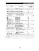
A094
Select method to switch to
Acc2/Dec2 profile
00 (switching by 2CH terminal), 01 (switching by setting),
02 (switching only when rotation is reversed)
00
¯
¯
A294
Select method to switch to
Acc2/Dec2, 2nd motor
00 (switching by 2CH terminal), 01 (switching by setting),
02 (switching only when rotation is reversed)
00
¯
¯
A095
Acc1 to Acc2 frequency transition point 0.00 to 99.99, 100.0 to 400.0 (Hz)
0.00
¯
¯
A295
Acc1 to Acc2 frequency transition
point, 2nd motor
0.00 to 99.99, 100.0 to 400.0 (Hz)
0.00
¯
¯
A096
Dec1 to Dec2 frequency transition
point
0.00 to 99.99, 100.0 to 400.0 (Hz)
0.00
¯
¯
A296
Dec1 to Dec2 frequency transition
point, 2nd motor
0.00 to 99.99, 100.0 to 400.0 (Hz)
0.00
¯
¯
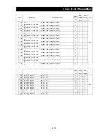
A097
Acceleration curve selection
00 (linear), 01 (S curve), 02 (U curve), 03 (inverted-U curve), 04 (EL-S curve)
00
¯
¯
4-31
A098
Deceleration curve setting
00 (linear), 01 (S curve), 02 (U curve), 03 (inverted-U curve), 04 (EL-S curve)
00
¯
¯
Exter
nal
fr
equ
ency adj
ustm
ent
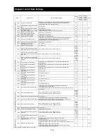
A101
[OI]-[L] input active range start
frequency
0.00 to 99.99, 100.0 to 400.0 (Hz)
0.00
¯
{
4-14
A102
[OI]-[L] input active range end
frequency
0.00 to 99.99, 100.0 to 400.0 (Hz)
0.00
¯
{
A103
[OI]-[L] input active range start current 0. to "[OI]-[L] input active range end current" (%)
20.
¯
{
A104
[OI]-[L] input active range end current
"[OI]-[L] input active range start current" to 100. (%)
100.
¯
{
A105
[OI]-[L] input start frequency enable
00 (external start frequency), 01 (0 Hz)
00
¯
{
A111
[O2]-[L] input active range start
frequency
-400. to -100., -99.9 to 0.00 to 99.99, 100.0 to 400.0 (Hz)
0.00
¯
{
A112
[O2]-[L] input active range end
frequency
-400. to -100., -99.9 to 0.00 to 99.99, 100.0 to 400.0 (Hz)
0.00
¯
{
A113
[O2]-[L] input active range start voltage -100. to 02 end-frequency rate (%)
-100.
¯
{
A114
[O2]-[L] input active range end voltage "02 start-frequency rate" to 100. (%)
100.
¯
{
n an
d
decel
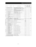
A131
Acceleration curve constants setting
01 (smallest swelling) to 10 (largest swelling)
02
¯
{
4-31
A132
Deceleration curve constants setting
01 (smallest swelling) to 10 (largest swelling)
02
¯
{
Oper
ati
on-
ta
rget fr
eq
uency
A141
Operation-target frequency selection 1
00 (digital operator), 01 (keypad potentiometer), 02 (input via O),
03 (input via OI), 04 (external communication), 05 (option 1), 06 (option 2),
07 (pulse-string frequency input)
02
¯
{
4-13
A142
Operation-target frequency selection 2
00 (digital operator), 01 (keypad potentiometer), 02 (input via O),
03 (input via OI), 04 (external communication), 05 (option 1), 06 (option 2),
07 (pulse-string frequency input)
03
¯
{
A143 Operator
selection
00 (addition: A141 + A142), 01 (subtraction: A141 - A142),
02 (multiplication: A141 x A142)
00
¯
{
A145
Frequency to be added
0.00 to 99.99, 100.0 to 400.0 (Hz)
0.00
¯
{
4-14
A146
Sign of the frequency to be added
00 (frequency c A145), 01 (frequency command - A145)
00
¯
{
Acceleratio
n
a
nd
decel
er
at
io
n
A150
EL-S-curve acceleration
ratio 1
0. to 50. (%)
25.
¯
¯
4-31
A151
EL-S-curve acceleration
ratio 2
0. to 50. (%)
25.
¯
¯
A152
EL-S-curve deceleration
ratio 1
0. to 50. (%)
25.
¯
¯
A153
EL-S-curve deceleration
ratio 2
0. to 50. (%)
25.
¯
¯
*1 This setting is valid only when the OPE-SR is connected.
Содержание L700 Series
Страница 16: ... Memo ...
Страница 20: ... Memo ...
Страница 22: ... Memo ...
Страница 46: ... Memo ...
Страница 60: ... Memo ...
Страница 62: ... Memo ...
Страница 212: ... Memo ...
Страница 222: ... Memo ...
Страница 224: ... Memo ...
Страница 232: ... Memo ...
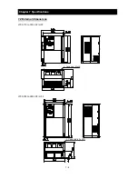
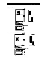
Страница 237: ...Chapter 7 Specifications 7 5 L700 300 LFF HFF L700 450 550 LFF HFF 750 HFF 5 Cable hole φ25 5 Cable hole φ41 ...
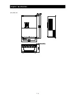
Страница 238: ...Chapter 7 Specifications 7 6 L700 750 LFF 6 Cable hole φ41 ...
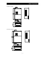
Страница 239: ...Chapter 7 Specifications 7 7 L700 900 to 1100HFF L700 1320 to 1600HFF ...
Страница 240: ... Memo ...
Страница 242: ... Memo ...
Страница 258: ... Memo ...