


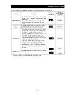


Chapter 5 Error Codes
5 - 9
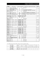
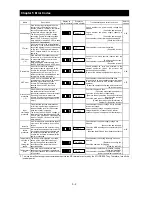
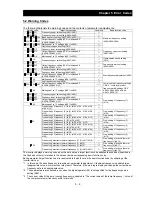
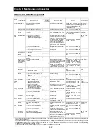
5.2 Warning Codes
The following table lists the warning codes and the contents of parameter readjustments:
Warning code
Target function code
Condition
Basic function code
001/ 201
Frequency upper limit setting (A061/A261)
>
Maximum frequency setting
(A004/A204/A304)
002/ 202
Frequency lower limit setting (A062/A262)
>
004/ 204/ 304 Base frequency setting (A003/A203/A303) (*1)
>
005/ 205/ 305
Output frequency setting (F001), multispeed 0
(A202/A220/A320) (*2)
>
006/ 206/ 306 Multispeed 1 to 15 settings (A021 to A035)
>
009
Home search speed setting (P015)
>
012/ 212
Fequency lower limit setting (A062/A262)
>
Frequency upper limit setting
(A061/A261)
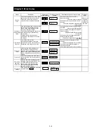
015/ 215
Output frequency setting (F001), multispeed 0
(A202/A220/A320) (*2)
>
016/ 216
Multispeed 1 to 15 settings (A021 to A035)
>
019
Frequency upper limit setting (A061/A261)
<
Home search speed setting
(P015)
021/ 221
<
Fequency lower limit setting
(A062/A262)
025/ 225
Output frequency setting (F001), multispeed 0
(A202/A220/A320) (*2)
<
031/ 231
Frequency upper limit setting (A061/A261)
<
Start frequency adjustment (b082)
032/ 232
Fequency lower limit setting (A062/A262)
<
035/ 235/ 335 Output frequency setting (F001), multispeed 0
(A202/A220/A320) (*2)
<
036
Multispeed 1 to 15 settings (A021 to A035)
<
037
Jog frequency setting (A038)
<
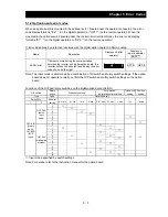
085/ 285/ 385
Output frequency setting (F001), multispeed 0
(A202/A220/A320) (*2)
<>
Jump (center) frequency settings
1/2/3 ± " Jump (hysteresis)
frequency width settings 1/2/3"
A063 ± A064, A065 ± A066,
A067 ± A068 (*3)
086
Multispeed 1 to 15 settings (A021 to A035)
<>
091/ 291
Frequency upper limit setting (A061/A261)
>
Free-setting V/f frequency (7)
(b112)
092/ 292
Fequency lower limit setting (A062/A262)
>
095/ 295
Output frequency setting (F001), multispeed 0
(A202/A220/A320) (*2)
>
096
Multispeed 1 to 15 settings (A021 to A035)
>
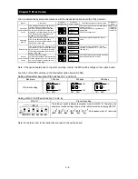
110
Free-setting V/f frequency (1) to (6) (b100, b102, b104, b106,
b108, b110)
>
Free-setting V/f frequency (2) to (6) (b102, b104, b106, b108,
b110)
<
Free-setting V/f frequency (1)
(b100)
Free-setting V/f frequency (1) (b100)
>
Free-setting V/f frequency (2)
(b102)
Free-setting V/f frequency (3) to (6) (b104, b106, b108, b110)
<
Free-setting V/f frequency (1) (2) (b100, b102)
>
Free-setting V/f frequency (3)
(b104)
Free-setting V/f frequency (4) to (6) (b106, b108, b110)
<
Free-setting V/f frequency (1) to (3) (b100, b102, b104, b110)
>
Free-setting V/f frequency (4)
(b106)
Free-setting V/f frequency (5) (6) (b108, b110)
<
Free-setting V/f frequency (1) to (4) (b100, b102, b104, b106)
>
Free-setting V/f frequency (5)
(b108)
Free-setting V/f frequency (6) (b110)
<
Free-setting V/f frequency (1) to (5) (b100, b102, b104, b106,
b108)
>
Free-setting V/f frequency (6)
(b110)
120
Free setting, electronic thermal frequency (2) (3) (b017/b019)
<
Free setting, electronic thermal
frequency (1) (b015)
Free setting, electronic thermal frequency (1) (b015)
>
Free setting, electronic thermal
frequency (2) (b017)
Free setting, electronic thermal frequency (3) (b019)
<
Free setting, electronic thermal frequency (1) (2) (b015/b017)
>
Free setting, electronic thermal
frequency (3) (b019)
The inverter displays a warning code when the data set as a target function code satisfies the condition (specified in
the Condition column) in relation to the data set as the corresponding basic function code.
Each parameter (target function code) is readjusted to the data set as the basic function code (by updating at the
inverter start-up).
*1 In this case, the base frequency is rewritten at parameter readjustment. If the base frequency is updated to an
inappropriate value, a motor burnout may result. Therefore, if the warning is displayed, change the current base
frequency data to an appropriate value.
*2 These parameters are checked, even when the digital operator (02) is not specified for the frequency source
setting (A001).
*3 The current value of the jump (center) frequency is updated to "'the current value of the jump frequency' - 'value of
the Jump (hysteresis) frequency width (minimum)'".
Содержание L700 Series
Страница 16: ... Memo ...
Страница 20: ... Memo ...
Страница 22: ... Memo ...
Страница 46: ... Memo ...
Страница 60: ... Memo ...
Страница 62: ... Memo ...
Страница 212: ... Memo ...
Страница 222: ... Memo ...
Страница 224: ... Memo ...
Страница 232: ... Memo ...
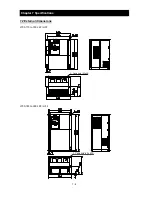
Страница 237: ...Chapter 7 Specifications 7 5 L700 300 LFF HFF L700 450 550 LFF HFF 750 HFF 5 Cable hole φ25 5 Cable hole φ41 ...
Страница 238: ...Chapter 7 Specifications 7 6 L700 750 LFF 6 Cable hole φ41 ...
Страница 239: ...Chapter 7 Specifications 7 7 L700 900 to 1100HFF L700 1320 to 1600HFF ...
Страница 240: ... Memo ...
Страница 242: ... Memo ...
Страница 258: ... Memo ...