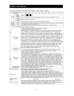


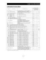

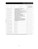


Chapter 8 List of Data Settings
8 - 6
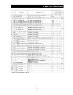
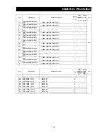
Code
Function name
Monitored data or setting
Default
Setting
during
operation
(allowed
or not)
Change
during
operation
(allowed
or not)
Page
_FF
R
e
st
ar
t af
ter
in
st
an
ta
ne
ous
pow
er
fa
ilu
re
or
tr
ippi
ng
b001
Selection of restart mode
00 (tripping), 01 (starting with 0 Hz), 02 (starting with matching frequency),
03 (tripping after deceleration and stopping with matching frequency),
04 (restarting with active matching frequency)
00
¯
{
4-33
b002
Allowable under-voltage power failure
time
0.3 to 25.0 (s)
1.0
¯
{
b003
Retry wait time before motor restart
0.3 to 100.0 (s)
1.0
¯
{
b004
Instantaneous power
failure/under-voltage trip alarm enable
00 (disabling), 01 (enabling),
02 (disabling during stopping and decelerating to stop)
00
¯
{
b005
Number of restarts on power
failure/under-voltage trip events
00 (16 times), 01 (unlimited)
00
¯
{
b006
Phase loss detection enable
00 (disabling), 01 (enabling)
00
¯
{
4-36
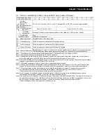
b007
Restart frequency threshold
0.00 to 99.99, 100.0 to 400.0 (Hz)
0.00
¯
{
4-33
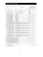
b008
Selection of retry after tripping
00 (tripping), 01 (starting with 0 Hz), 02 (starting with matching frequency),
03 (tripping after deceleration and stopping with matching frequency),
04 (restarting with active matching frequency)
00
¯
{
b009
Selection of retry after undervoltage
00 (16 times), 01 (unlimited)
00
¯
{
b010
Selection of retry count after
overvoltage or overcurrent
1 to 3 (times)
3
¯
{
b011
Retry wait time after tripping
0.3 to 100.0 (s)
1.0
¯
{
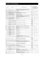
El
ectr
oni
c t
h
er
m
a
l f
u
nc
tion
b012
Electronic thermal setting (calculated
within the inverter from current output)
0.20 x "rated current" to 1.00 x "rated current" (A)
Rated
current
of
inverter
¯
{
4-37
b212
Electronic thermal setting (calculated
within the inverter from current output),
2nd motor
0.20 x "rated current" to 1.00 x "rated current" (A)
Rated
current
of
inverter
¯
{
b312
Electronic thermal setting (calculated
within the inverter from current output),
3rd motor
0.20 x "rated current" to 1.00 x "rated current" (A)
Rated
current
of
inverter
¯
{
b013 Electronic thermal characteristic
00 (reduced-torque characteristic), 01 (constant-torque characteristic),
02 (free setting)
01
¯
{
b213
Electronic thermal characteristic,
2nd motor
00 (reduced-torque characteristic), 01 (constant-torque characteristic),
02 (free setting)
01
¯
{
b313
Electronic thermal characteristic,
3rd motor
00 (reduced-torque characteristic), 01 (constant-torque characteristic),
02 (free setting)
01
¯
{
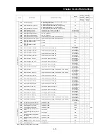
b015
Free setting, electronic thermal
frequency (1)
0. to 400. (Hz)
0.
¯
{
4-38
b016
Free setting, electronic thermal
current (1)
0.0 to rated current (A)
0.0
¯
{
b017
Free setting, electronic thermal
frequency (2)
0. to 400. (Hz)
0.
¯
{
b018
Free setting, electronic thermal
current (2)
0.0 to rated current (A)
0.0
¯
{
b019
Free setting, electronic thermal
frequency (3)
0. to 400. (Hz)
0.
¯
{
b020
Free setting, electronic thermal
current (3)
0.0 to rated current (A)
0.0
¯
{
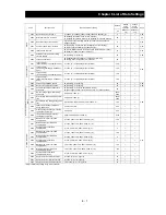
Over
load r
e
str
icti
on
an
d over
cur
re
nt r
e
str
a
in
t
b021
Overload restriction operation mode
00 (disabling), 01 (enabling during acceleration and deceleration),
02 (enabling during constant speed),
03 (enabling during acceleration and deceleration (increasing the speed during
regeneration))
01
¯
{
4-40
b022
Overload restriction setting
0.20 x "rated current" to 1.50 x "rated current" (A)
<0.20 x "rated current" to1.50 x "rated current" (A)>
Rated
current
of
inverter
x 1.20
¯
{
b023
Deceleration rate at overload restriction 0.10 to 30.00 (s)
1.00
¯
{
b024
Overload restriction operation mode (2)
00 (disabling), 01 (enabling during acceleration and deceleration),
02 (enabling during constant speed), 03 (enabling during acceleration and
deceleration (increasing the speed during regeneration))
01
¯
{
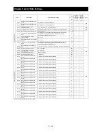
b025
Overload restriction setting (2)
0.20 x "rated current" to 1.50 x "rated current" (A)
<0.20 x "rated current" to1.50 x "rated current" (A)>
Rated
current
of
inverter
x 1.20
¯
{
b026
Deceleration rate at overload restriction (2) 0.10 to 30.00 (s)
1.00
¯
{
b027
Overcurrent suppression enable
00 (disabling), 01 (enabling)
01
¯
{
4-41
b028
Active frequency matching, scan start
frequency
0.20 x "rated current" to 1.50 x "rated current" (A)
<0.20 x "rated current" to1.50 x "rated current" (A)>
Rated
current
of
inverter
¯
{
4-33
b029
Active frequency matching, scan-time
constant
0.10 to 30.00 (s)
0.50
¯
{
b030
Active frequency matching, restart
frequency select
00 (frequency at the last shutoff), 01 (maximum frequency),
02 (set frequency)
00
¯
{
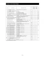
S
o
ftwa
re
lo
ck
b031
Software lock mode selection
00 (disabling change of data other than "b031" when SFT is on),
01 (disabling change of data other than "b031" and frequency settings when SFT
is on),
02 (disabling change of data other than "b031"),
03 (disabling change of data other than "b031" and frequency settings),
10 (enabling data changes during operation)
01
¯
{
4-52
(Note)<>indicate the setting range of 90 to 160kW
Содержание L700 Series
Страница 16: ... Memo ...
Страница 20: ... Memo ...
Страница 22: ... Memo ...
Страница 46: ... Memo ...
Страница 60: ... Memo ...
Страница 62: ... Memo ...
Страница 212: ... Memo ...
Страница 222: ... Memo ...
Страница 224: ... Memo ...
Страница 232: ... Memo ...
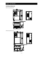
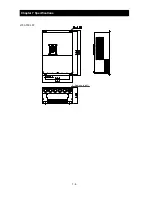
Страница 237: ...Chapter 7 Specifications 7 5 L700 300 LFF HFF L700 450 550 LFF HFF 750 HFF 5 Cable hole φ25 5 Cable hole φ41 ...
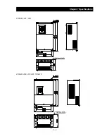
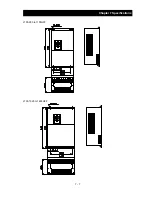
Страница 238: ...Chapter 7 Specifications 7 6 L700 750 LFF 6 Cable hole φ41 ...
Страница 239: ...Chapter 7 Specifications 7 7 L700 900 to 1100HFF L700 1320 to 1600HFF ...
Страница 240: ... Memo ...
Страница 242: ... Memo ...
Страница 258: ... Memo ...