


Chapter 4 Explanation of Functions
4 - 87
3) If "01" (enabling) is specified for the DC braking enable (A051), motor constants cannot be measured by
offline auto-tuning. Specify "00" (disabling) for the DC braking enable. (The default setting is "00".)
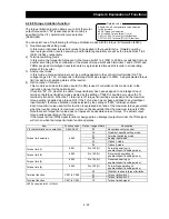
4) If "02" (auto-tuning with motor rotation) is specified for the Auto-tuning Setting (H001), confirm or
observe the following:
a) No problem occurs when the motor rotates at a speed close to 80% of the base frequency.
b) The motor is not driven by any other external power source.
c) All brakes are released.
d) During auto-tuning, insufficient torque may cause a problem in the load driven by the motor (for
example, a lift may slide down). Therefore, remove the motor from the machine or other load, and
perform auto-tuning with the motor alone. (The moment of inertia [J] measured by auto-tuning is that of
the motor alone. To apply the data, add the moment of inertia of the load machine to the measured J
data after converting the moment of inertia into the motor shaft data.)
e) If the motor is installed in a machine (e.g., lift or boring machine) that limits the motor shaft rotation, the
allowable rotation limit may be exceeded during auto-tuning, and the machine may be damaged. To
avoid this problem, specify "01" (auto-tuning without motor rotation) for the Auto-tuning Setting (H001).
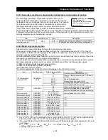
f) If the no-load current is unknown, operate the motor at 50 Hz in a V/f characteristic control mode to
measure the motor current with current monitor. Then, set the measured current as the control
constant "H023" or "H223" before auto-tuning.
5) Even when "01" (auto-tuning without motor rotation) is specified for the Auto-tuning Setting (H001), the
motor may rotate slightly during auto-tuning.
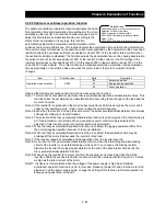
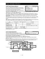
6) When performing the auto-tuning for a motor of which the capacity is one class lower than that of the
inverter, enable the overload restriction function, and set the overload restriction level to 1.5 times as
high as the rated current of the motor.
Operating procedure
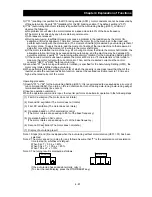
1) Specify "01" or "02" for the Auto-tuning Setting (H001). It is recommended to use keypad as a source of
run command (A002). If you turn on the run command or turn off during auto-tuning, auto-tuning will get
terminated abnormally. (see note 5)
2) Input an operation command.
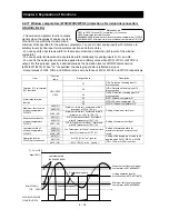
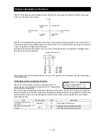
When the operation command is input, the inverter performs an automatic operation in the following steps:
(1) First AC excitation (The motor does not rotate.)
↓
(2) Second AC excitation (The motor does not rotate.)
↓
(3) First DC excitation (The motor does not rotate.)
↓
(4) Operation based on V/f characteristic control
(The motor rotates at a speed up to 80% of the base frequency.)
↓
(5) Operation based on SLV control
(The motor rotates at a speed up to x% of the base frequency.)
↓
(6) Second DC excitation (The motor does not rotate.)
↓
(7) Display of auto-tuning result
Note 1: Steps (4) and (5) are skipped when the auto-tuning without motor rotation (H001 = 01) has been
selected.
Note 2: The motor speed (x) in step (5) is as follows. Assume that "T" is the acceleration or deceleration
time in step (4), whichever is largest.
When
0s
≤
T < 50 s, x = 40%.
When 50 s
≤
T < 100 s, x = 20%.
When
100
s
≤
T, x = 10%.
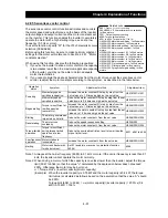
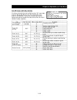
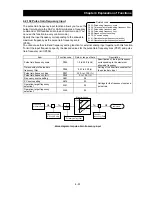
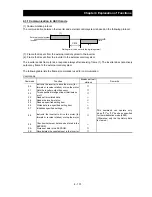
Note 3: The tuning result is displayed as follows:
If the auto-tuning has ended abnormally, retry it.
(To clear the result display, press the STOP/RESET key.)
Normal end
Abnormal end
Содержание L700 Series
Страница 16: ... Memo ...
Страница 20: ... Memo ...
Страница 22: ... Memo ...
Страница 46: ... Memo ...
Страница 60: ... Memo ...
Страница 62: ... Memo ...
Страница 212: ... Memo ...
Страница 222: ... Memo ...
Страница 224: ... Memo ...
Страница 232: ... Memo ...
Страница 237: ...Chapter 7 Specifications 7 5 L700 300 LFF HFF L700 450 550 LFF HFF 750 HFF 5 Cable hole φ25 5 Cable hole φ41 ...
Страница 238: ...Chapter 7 Specifications 7 6 L700 750 LFF 6 Cable hole φ41 ...
Страница 239: ...Chapter 7 Specifications 7 7 L700 900 to 1100HFF L700 1320 to 1600HFF ...
Страница 240: ... Memo ...
Страница 242: ... Memo ...
Страница 258: ... Memo ...