


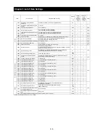
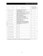


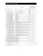
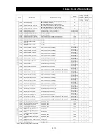


Chapter 8 List of Data Settings
8 - 9
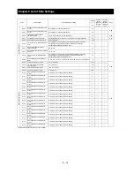
Code
Function name
Monitored data or setting
Default
Setting
during
operation
(allowed
or not)
Change
during
operation
(allowed
or not)
Page
_FF
In
te
llig
en
t inp
u
t te
rmina
ls
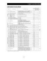
C001
Terminal [1] function (*2)
01 (RV: Reverse RUN), 02 (CF1: Multispeed 1 setting),
03 (CF2: Multispeed 2 setting), 04 (CF3: Multispeed 3 setting),
05 (CF4: Multispeed 4 setting), 06 (JG: Jogging),
07 (DB: external DC braking),
08 (SET: Set 2nd motor data), 09 (2CH: 2-stage acceleration/deceleration),
11 (FRS: free-run stop), 12 (EXT: external trip),
13 (USP: unattended start protection), 14: (CS: commercial power source
enable), 15 (SFT: software lock), 16 (AT: analog input voltage/current select),
17 (SET3: 3rd motor control), 18 (RS: reset),
20 (STA: starting by 3-wire input), 21 (STP: stopping by 3-wire input),
22 (F/R: forward/reverse switching by 3-wire input), 23 (PID: PID disable),
24 (PIDC: PID reset), 26 (CAS: control gain setting),
27 (UP: remote control UP function),
28 (DWN: remote control DOWN function),
29 (DWN: remote control data clearing), 31 (OPE: forcible operation),
32 (SF1: multispeed bit 1), 33 (SF2: multispeed bit 2),
34 (SF3: multispeed bit 3), 35 (SF4: multispeed bit 4),
36 (SF5: multispeed bit 5), 37 (SF6: multispeed bit 6),
38 (SF7: multispeed bit 7), 39 (OLR: overload restriction selection),
40 (TL: torque limit enable), 41 (TRQ1: torque limit selection bit 1),
42 (TRQ2: torque limit selection bit 2), 43 (PPI: P/PI mode selection),
46 (LAC: LAD cancellation),
50 (ADD: trigger for frequency addition [A145]),
51 (F-TM: forcible-terminal operation),
53 (KHC: cumulative power clearance),
56 (MI1: general-purpose input 1), 57 (MI2: general-purpose input 2),
58 (MI3: general-purpose input 3), 59 (MI4: general-purpose input 4),
60 (MI5: general-purpose input 5), 61 (MI6: general-purpose input 6),
62 (MI7: general-purpose input 7), 63 (MI8: general-purpose input 8),
64(EMR: Emergency stop signal),65 (AHD: analog command holding),
74 (PCNT: pulse counter), 75 (PCC: pulse counter clear),
no (NO: no assignment)
18
(*2)
¯
{
4-47
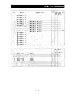
C002
Terminal [2] function
16
¯
{
C003
Terminal [3] function (*2)
03
(*2)
¯
{
C004
Terminal [4] function
02
¯
{
C005
Terminal [5] function
01
¯
{
C006
Terminal [6] function
06
¯
{
C007
Terminal [7] function
11
¯
{
C008
Terminal [8] function
13
¯
{
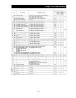
C011
Terminal [1] active state
00 (NO) / 01 (NC)
00
¯
{
4-48
C012
Terminal [2] active state
00 (NO) / 01 (NC)
00
¯
{
C013
Terminal [3] active state
00 (NO) / 01 (NC)
00
¯
{
C014
Terminal [4] active state
00 (NO) / 01 (NC)
00
¯
{
C015
Terminal [5] active state
00 (NO) / 01 (NC)
00
¯
{
C016
Terminal [6] active state
00 (NO) / 01 (NC)
00
¯
{
C017
Terminal [7] active state
00 (NO) / 01 (NC)
00
¯
{
C018
Terminal [8] active state
00 (NO) / 01 (NC)
00
¯
{
C019
Terminal [FW] active state
00 (NO) / 01 (NC)
00
¯
{
*2
When the emergency stop function is enabled (SW1 = ON), "18" (RS) and "64" (EMR) are forcibly written to parameters "C001" and "C003", respectively. (You cannot
arbitrarily write "64" to "C001".) If the SW1 signal is turned off and then turned on, "no" (no assignment) is set in parameter "C003".
Содержание L700 Series
Страница 16: ... Memo ...
Страница 20: ... Memo ...
Страница 22: ... Memo ...
Страница 46: ... Memo ...
Страница 60: ... Memo ...
Страница 62: ... Memo ...
Страница 212: ... Memo ...
Страница 222: ... Memo ...
Страница 224: ... Memo ...
Страница 232: ... Memo ...
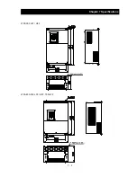
Страница 237: ...Chapter 7 Specifications 7 5 L700 300 LFF HFF L700 450 550 LFF HFF 750 HFF 5 Cable hole φ25 5 Cable hole φ41 ...
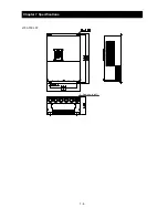
Страница 238: ...Chapter 7 Specifications 7 6 L700 750 LFF 6 Cable hole φ41 ...
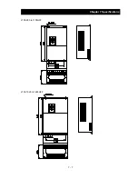
Страница 239: ...Chapter 7 Specifications 7 7 L700 900 to 1100HFF L700 1320 to 1600HFF ...
Страница 240: ... Memo ...
Страница 242: ... Memo ...
Страница 258: ... Memo ...