


Chapter 2 Installation and Wiring
2 - 14
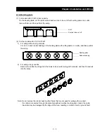
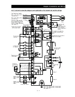
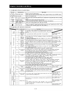
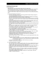
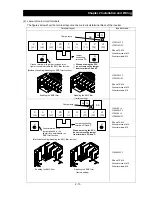
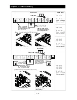
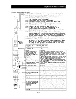
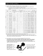
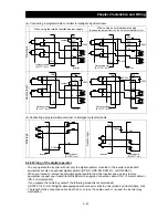
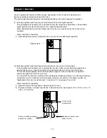
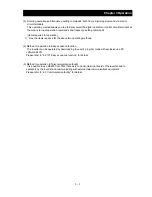
Terminal layout
Inverter model
R
(L1)
S
(L2)
T
(L3)
PD
(+1)
P
(+)
N
(‑)
U
(T1)
V
(T2)
W
(T3)
R0 T0
G
G
L700-370LFF
R0 and T0: M4
Ground terminal: M6
Other terminals: M8
L700-370HFF
R0 and T0: M4
Ground terminal: M6
Other terminals: M6
L700-450LFF
L700-450HFF
R0 and T0: M4
Ground terminal: M8
Other terminals: M8
R
(L1)
S
(L2)
T
(L3)
PD
(+1)
P
(+)
N
(‑)
U
(T1)
V
(T2)
W
(T3)
R0 T0
charge lump
G
G
L700-550LFF
L700-550HFF
L700-750HFF
R0 and T0: M4
Ground terminal: M8
Other terminals: M8
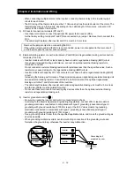
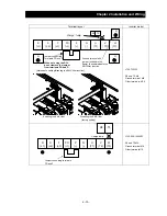
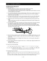
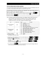
[Method of enabling/disabling the EMC filter function]
Enabling the EMC filter
Disabling the EMC filter
(factory setting)
Charge lamp
When not using the DCL,
do not remove the jumper
from terminals PD and P.
Ground terminal with
jumper (shaded in the
figure) to enable/disable the
EMC filter function
Jumper connecting
terminals PD and P
[Method of enabling/disabling the EMC filter function]
Enabling the EMC filter
Disabling the EMC filter
(factory setting )
When not using the DCL,
do not remove the jumper
from terminals PD and P.
Ground terminal with
jumper (shaded in the
figure) to enable/disable the
EMC filter function
G
Jumper connecting
Terminals PD and P
Содержание L700 Series
Страница 16: ... Memo ...
Страница 20: ... Memo ...
Страница 22: ... Memo ...
Страница 46: ... Memo ...
Страница 60: ... Memo ...
Страница 62: ... Memo ...
Страница 212: ... Memo ...
Страница 222: ... Memo ...
Страница 224: ... Memo ...
Страница 232: ... Memo ...
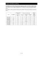
Страница 237: ...Chapter 7 Specifications 7 5 L700 300 LFF HFF L700 450 550 LFF HFF 750 HFF 5 Cable hole φ25 5 Cable hole φ41 ...
Страница 238: ...Chapter 7 Specifications 7 6 L700 750 LFF 6 Cable hole φ41 ...
Страница 239: ...Chapter 7 Specifications 7 7 L700 900 to 1100HFF L700 1320 to 1600HFF ...
Страница 240: ... Memo ...
Страница 242: ... Memo ...
Страница 258: ... Memo ...