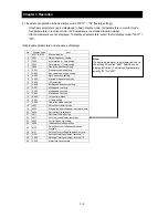


Chapter 4 Explanation of Functions
4 - 4
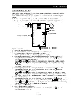
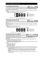
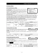
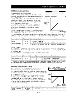
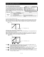
4.1.13 Cumulative power-on time monitoring
When the cumulative power-on time monitoring function(d017) is selected,
the inverter displays the cumulative time throughout which the inverter
power has been on.
(Display)
0. to 9999. in units of 1 hour
1000 to 9999 in units of 10 hours
⎡
100 to
⎡
999 in units of 1,000 hours
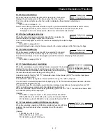
4.1.14 Heat sink temperature monitoring
When the heat sink temperature monitoring function (d018) is selected,
the inverter displays the temperature of the internal heat sink of the
inverter.
(Display)
0.0 to 200.0 in steps of 0.1 °C
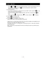
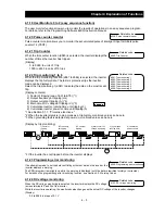
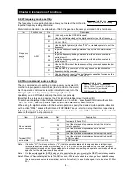
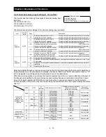
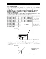
4.1.15 Motor temperature monitoring
When the motor temperature monitoring function is selected, the inverter
displays the temperature of the thermistor connected between control
circuit terminals TH and CM1.
Use the thermistor model PB-41E made by Shibaura Electronics Corporation.
Specify "02" (enabling NTC) for the thermistor for thermal protection control (function "b098").
(Display)
0.0 to 200.0 in steps of 0.1 °C.
Note: If "01" (enabling PTC) is specified for the thermistor for thermal protection control (function "b098"),
motor temperature monitoring is disabled.
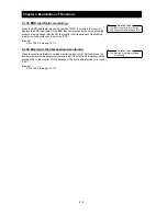
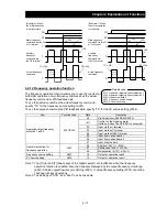
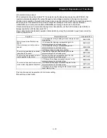
4.1.16 Life-check monitoring
When the life-check monitoring function (d002) is selected, the inverter
displays the operating life status of two inverter parts output from
corresponding intelligent output terminals by using LED segments of the
monitor.
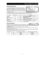
The two targets of life-check monitoring are:
1: Life of the capacitor on the main circuit board
2: Degradation of cooling fan speed
Note 1: The inverter estimates the capacitor life every 10 minutes. If you turn the inverter power on and off
repeatedly at intervals of less than 10 minutes, the capacitor life cannot be checked correctly.
Note 2: If you have specified "01" for the selection of cooling fan operation (function "b0092"), the inverter
determines the cooling fan speed to be normal while the cooling fan is stopped.
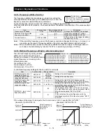
4.1.17 Program counter display (easy sequence function)
While the easy sequence function is operating, the inverter displays the
program line number that is being executed.
For details, refer to the “Programming Software EzSQ” manual.
4.1.18 Program number monitoring (easy sequence function)
When the program number monitoring function (d024) is selected, the
inverter displays the program number of the downloaded easy sequence
program.
Note that you must describe a program number in the program you create. For details, refer to the
“Programming Software EzSQ” manual.
d017: Cumulative power-on time
monitoring
Related code
d019: Motor temperature monitoring
b098: Thermistor for thermal
protection control
Related code
d022: Life-check monitoring
Related code
1
2
Life check
Normal
d023: Program counter
Related code
d024: Program number monitoring
Related code
d018: Heat sink temperature
monitoring
Related code
d025: user monitor 0
d026: user monitor 1
d027: user monitor 2
Related code
Содержание L700 Series
Страница 16: ... Memo ...
Страница 20: ... Memo ...
Страница 22: ... Memo ...
Страница 46: ... Memo ...
Страница 60: ... Memo ...
Страница 62: ... Memo ...
Страница 212: ... Memo ...
Страница 222: ... Memo ...
Страница 224: ... Memo ...
Страница 232: ... Memo ...
Страница 237: ...Chapter 7 Specifications 7 5 L700 300 LFF HFF L700 450 550 LFF HFF 750 HFF 5 Cable hole φ25 5 Cable hole φ41 ...
Страница 238: ...Chapter 7 Specifications 7 6 L700 750 LFF 6 Cable hole φ41 ...
Страница 239: ...Chapter 7 Specifications 7 7 L700 900 to 1100HFF L700 1320 to 1600HFF ...
Страница 240: ... Memo ...
Страница 242: ... Memo ...
Страница 258: ... Memo ...