


Chapter 4 Explanation of Functions
4 - 42
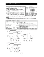
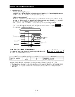
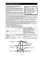
4.2.32 Over voltage supression during deceleration
- The over voltage supression function allows you to prevent the
inverter from tripping because of the overvoltage that can be caused by
the energy regenerated by the motor during deceleration.
- You can enable or disable the function by setting the overvoltage
suppression enable (b130).
- When "01" (enabling the over voltage supression [with deceleration stop]) is specified for the overvoltage
suppression enable (b130), the inverter will decelerate by keeping the voltage of the main circuit DC
section at over voltage suppression level (b131).
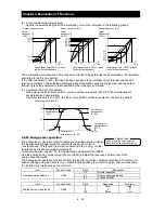
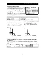
- When "02" (enabling the overvoltage suppression [with acceleration]) is specified for the overvoltage
suppression enable (b130), the inverter will start acceleration according to the acceleration and
deceleration rate at overvoltage suppression (b132) if the voltage of the main circuit DC section exceeds
the overvoltage suppression level (b131). Subsequently, the inverter will restart deceleration when the
voltage falls below the level (b131).
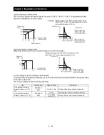
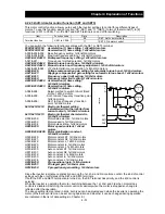
Item
Function code
Data or range of data
Description
Overvoltage suppression
enable
b130
00 Disable
01
Enabling the overvoltage suppression
(with controlled deceleration) (See
example 1.) (note5)
02
Enabling the overvoltage suppression
(with acceleration) (See example 2.)
Overvoltage suppression
level (See Note 4.)
b131
330 to 390 (V)
Level setting for 200 V class models
660 to 780 (V)
Level setting for 400 V class models
Acceleration rate at
overvoltage suppression
b132
0.10 to 30.00 (s)
Specifying the acceleration rate to be
applied when the function is enabled
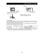
Overvoltage suppression
propotional gain
b134
0 to 255
Overvoltage suppression propotional gain
setting (valid when b130=01)
Overvoltage suppression
integral time
b135
0 to 65535
Overvoltage suppression integral time
setting (valid when b130=01)
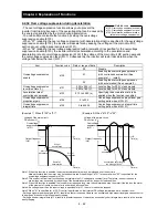
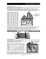
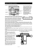
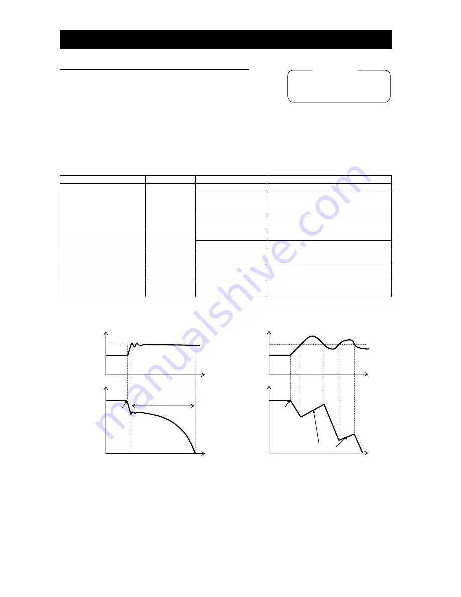
(Example 1) When "b130" is "01":
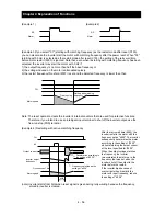
(Example 2) When "b130" is "02":
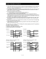
Note 1:When this function is enabled, the actual acceleration time may be prolonged over the set time.
Note particularly that the motor may not be decelerated if the setting of "b131" is too small when "02" is specified for the
overvoltage suppression enable (b130).
Note 2:This overcurrent restraint function does not maintain the DC voltage at a constant level. Therefore, inverter trips due to
overvoltage may be caused by the setting of the deceleration rate or by a specific load condition.
Note 3:When this function is enabled, the inverter may requires a long time to decelerate and stop the motor if the load on the motor
or the moment of inertia on the motor is under a specific condition.
Note 4:If a voltage lower than the input voltage is specified for b131, the motor cannot be stopped.
Note 5:When "01" is specified for b130, PI control is performed so that internal DC voltage is maintained at a constant level.
- Setting a higher proportional gain (b133) results in a faster response. However, an excessively high proportional gain causes control
to diverge and results in the inverter easily tripping.
- Setting a shorter integral time (b134) results in a faster response. However, an excessively short integral time results in the inverter
easily tripping.
b130: Overvoltage suppression enable
b131: Overvoltage suppression level
b132: Acceleration and deceleration
rate at overvoltage suppression
Related code
Voltage of the main circuit
DC section (V)
Overvoltage
suppression level
(b131)
Output frequency
(Hz)
Voltage of the main circuit
DC section (V)
Overvoltage
suppression level
(b131)
Output frequency
(Hz)
Start of
deceleration
Stop of
deceleration
Restart of
deceleration
Stop of
deceleration
Time (s)
Start of
deceleration
Acceleration according to
the setting of "b132"
Time (s)
Time (s)
Time (s)
Содержание L700 Series
Страница 16: ... Memo ...
Страница 20: ... Memo ...
Страница 22: ... Memo ...
Страница 46: ... Memo ...
Страница 60: ... Memo ...
Страница 62: ... Memo ...
Страница 212: ... Memo ...
Страница 222: ... Memo ...
Страница 224: ... Memo ...
Страница 232: ... Memo ...
Страница 237: ...Chapter 7 Specifications 7 5 L700 300 LFF HFF L700 450 550 LFF HFF 750 HFF 5 Cable hole φ25 5 Cable hole φ41 ...
Страница 238: ...Chapter 7 Specifications 7 6 L700 750 LFF 6 Cable hole φ41 ...
Страница 239: ...Chapter 7 Specifications 7 7 L700 900 to 1100HFF L700 1320 to 1600HFF ...
Страница 240: ... Memo ...
Страница 242: ... Memo ...
Страница 258: ... Memo ...