


Index
Index - 1
A
a/b ............................................................ 4-48, 4-63
acceleration/deceleration patterns .................... 4-31
acceleration curve constant .............................. 4-31
acceleration time ...................................... 4-10, 4-30
acceleration (2) time ......................................... 4-30
acceleration stop ............................................... 4-25
ADD .................................................................. 4-14
AHD .................................................................. 4-61
AL ..................................................................... 4-62
alarm code output ............................................. 4-68
alarm relay terminal function ............................. 4-63
allowable under-voltage power failure
time ............................................................. 4-33
AM ............................................................. 2-8, 4-77
AMI ............................................................ 2-8, 4-77
analog command holding .................................. 4-61
analog input filter ............................................... 4-15
ascii mode ....................................................... 4-101
AT .............................................................. 2-8, 4-12
automatic carrier frequency reduction ............... 4-45
automatic torque boost ..................................... 4-18
AVR ................................................................... 4-11
AVR voltage select ................................... 4-11, 4-15
B
basic display ..................................................... 4-79
base frequency ................................................. 4-11
binary operation ....................................... 4-48, 4-49
bit operation ............................................. 4-48, 4-49
BRD ......................................................... 2-12, 4-46
BRD load factor monitoring ................................. 4-6
C
capacitor life warning ........................................ 4-70
carrier frequency ............................................... 4-44
CAS .................................................................. 4-59
CE ................................................................... 2-18
CF1, CF2, CF3, CF4 ......................................... 4-48
CM1 ........................................................... 2-8, 2-21
commercial power supply switching .................. 4-54
communication function ........................... 4-70, 4-98
communication line disconnection
signal ........................................................... 4-70
constant-torque characteristic
(electronic thermal) ...................................... 4-37
constant-torque characteristic (VC) .......... 4-16, 4-89
control circuit terminal ......................................... 2-8
control gain switching ........................................ 4-59
control mode ..................................................... 4-16
cooling-fan operation ............................... 4-46, 4-71
cooling-fan speed drop signal ........................... 4-71
copying .............................................................. A-1
counterrotation prevention ................................ 4-92
CS ..................................................................... 4-54
cumulative power monitoring .............................. 4-3
cumulative power-on time monitoring ........ 4-4, 4-66
cumulative running time ...................................... 4-3
2CH ................................................................... 4-30
D
data comparison display ................................... 4-80
DB ..................................................................... 4-20
DC braking ....................................................... 4-20
DC voltage monitoring ........................................ 4-5
deceleration (2) time setting ............................. 4-30
deceleration and stopping at power
failure .......................................................... 4-84
deceleration curve constant .............................. 4-31
deceleration overvoltage restraint ..................... 4-42
deceleration time .............................................. 4-10
derating ............................................................ 4-44
detection of terminal disconnection .................. 4-74
digital operator ........................................... 2-21, 3-4
display of trip monitoring .............................. 4-5, 5-8
DWN ................................................................. 4-57
E
easy sequence .......................................... 4-5, 4-96
electronic thermal ............................................. 4-37
electronic thermal overload monitoring ............... 4-6
electronic thermal warning level setting ............ 4-39
EMC ............................................ safety instructions
emergency stop .............................................. 4-148
EMR ............................................................... 4-148
end frequency ................................................... 4-14
end-frequency rate ........................................... 4-15
energy-saver operation ..................................... 4-32
excessive speed ................................................. 5-5
extended function mode ..................................... 3-9
external analog input ........................................ 4-12
external DC braking .......................................... 4-20
external thermistor ............................................ 4-75
external trip ....................................................... 4-58
F
F/R .................................................................... 4-58
F-TM ................................................................. 4-52
factory default(setting) .................................... 4-78
FA1, FA2, FA3, FA4, FA5 .................................. 4-64
FBV ......................................................... 4-26, 4-29
feedback .................................................... 4-1, 4-28
feed forward selection ...................................... 4-28
FM ............................................................. 2-8, 4-76
FOC .................................................................. 4-92
forcible operation .............................................. 4-52
forcible-terminal operation ................................ 4-52
forcing ............................................................... 4-92
forward rotation signal ...................................... 4-72
FR ..................................................................... 4-71
free setting of electronic thermal
characteristic ............................................... 4-38
free V/f characteristic ........................................ 4-17
free-run stop .............................................. 4-9, 4-53
frequency addition ............................................ 4-14
frequency arrival setting for accel. .................... 4-64
frequency arrival setting for decel. .................... 4-64
frequency limit .................................................. 4-24
frequency lower limit ......................................... 4-24
frequency matching ...................... 4-33, 4-53, 4-55
frequency operation .......................................... 4-13
frequency reached signal ................................. 4-64
frequency scaling conversion factor ................... 4-2
frequency source setting .................................... 4-8
frequency to be added ...................................... 4-14
frequency upper limit ........................................ 4-24
FRS .................................................................. 4-53
function code display restriction................. 3-4, 4-79
Содержание L700 Series
Страница 16: ... Memo ...
Страница 20: ... Memo ...
Страница 22: ... Memo ...
Страница 46: ... Memo ...
Страница 60: ... Memo ...
Страница 62: ... Memo ...
Страница 212: ... Memo ...
Страница 222: ... Memo ...
Страница 224: ... Memo ...
Страница 232: ... Memo ...
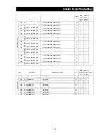
Страница 237: ...Chapter 7 Specifications 7 5 L700 300 LFF HFF L700 450 550 LFF HFF 750 HFF 5 Cable hole φ25 5 Cable hole φ41 ...
Страница 238: ...Chapter 7 Specifications 7 6 L700 750 LFF 6 Cable hole φ41 ...
Страница 239: ...Chapter 7 Specifications 7 7 L700 900 to 1100HFF L700 1320 to 1600HFF ...
Страница 240: ... Memo ...
Страница 242: ... Memo ...
Страница 258: ... Memo ...