


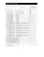


Chapter 8 List of Data Settings
8 - 11
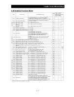
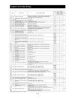
Code
Function name
Monitored data or setting
Default
Setting
during
operation
(allowed
or not)
Change
during
operation
(allowed
or not)
Page
_FF
Level
s
and
ou
tpu
t ter
m
inal
st
atus
C038
Low-current indication signal output
mode selection
00 (output during acceleration/deceleration and constant-speed
operation), 01 (output only during constant-speed operation)
01
¯
{
4-72
C039
Low-current indication signal
detection level
0.0 to 1.50 x "rated current" (A)
Rated
current
of
inverter
{
{
C040
Overload signal output mode
00 (output during acceleration/deceleration and constant-speed
operation), 01 (output only during constant-speed operation)
01
¯
{
4-40
C041
Overload level setting
0.0 to 1.50 x "rated current" (A) <0.0 to 1.50 x "rated current">
Rated
current
of
inverter
{
{
C042
Frequency arrival setting for accel.
0.00 to 99.99, 100.0 to 400.0 (Hz)
0.00
¯
{
4-64
C043
Frequency arrival setting for decel.
0.00 to 99.99, 100.0 to 400.0 (Hz)
0.00
¯
{
C044
PID deviation level setting
0.0 to 100.0 (%)
3.0
¯
{
4-26
C045
Frequency arrival setting for
acceleration (2)
0.00 to 99.99, 100.0 to 400.0 (Hz)
0.00
¯
{
4-64
C046
Frequency arrival setting for
deceleration (2)
0.00 to 99.99, 100.0 to 400.0 (Hz)
0.00
¯
{
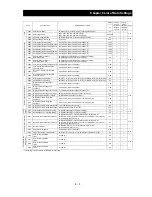
C052
Maximum PID feedback data
0.0 to 100.0 (%)
100.0
¯
{
4-26
C053
Minimum PID feedback data
0.0 to 100.0 (%)
0.0
¯
{
C055
Over-torque (forward-driving)
level setting
0. to 150. (%)
100.
¯
{
4-67
C056
Over-torque (reverse regenerating)
level setting
0. to 150. (%)
100.
¯
{
C057
Over-torque (reverse driving)
level setting
0. to 150. (%)
100.
¯
{
C058
Over-torque (forward regenerating)
level setting
0. to 150. (%)
100.
¯
{
C061
Electronic thermal warning
level setting
0. to 100. (%)
80.
¯
{
4-37
C062
Alarm code output
00 (disabling), 01 (3 bits), 02 (4 bits)
00
¯
{
4-68
C063
Zero speed detection level
0.00 to 99.99, 100.0 (Hz)
0.00
¯
{
4-66
C064
Heat sink overheat warning level
0. to 200.0 (
°
C)
120.
¯
{
4-71
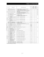
C
o
m
m
uni
cati
on
fu
ncti
on
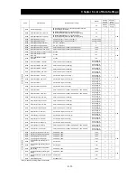
C071 Communication
speed
selection
02 (loopback test), 03 (2,400 bps), 04 (4,800 bps), 05 (9,600 bps),
06 (19,200 bps)
04
¯
{
4-97
C072
Node allocation
1. to 32.
1.
¯
{
C073
Communication data length selection
7 (7 bits), 8 (8 bits)
7
¯
{
C074
Communication parity selection
00 (no parity), 01 (even parity), 02 (odd parity)
00
¯
{
C075
Communication stop bit selection
1 (1 bit), 2 (2 bits)
1
¯
{
C076
Selection of the operation after
communication error
00 (tripping), 01 (tripping after decelerating and stopping the motor),
02 (ignoring errors), 03 (stopping the motor after free-running),
04 (decelerating and stopping the motor)
02
¯
{
C077
Communication timeout limit before
tripping
0.00 to 99.99 (s)
0.00
¯
{
C078
Communication wait time
0. to 1000. (ms)
0.
¯
{
C079
Communication mode selection
00(ASCII), 01(Modbus-RTU)
00
¯
{
Adjustme
nt
C081
[O] input span calibration
0. to 9999., 1000 to 6553(10000 to 65530)
Factory
setting
{
{
−
C082
[OI] input span calibration
0. to 9999., 1000 to 6553(10000 to 65530)
Factory
setting
{
{
C083
[O2] input span calibration
0. to 9999., 1000 to 6553(10000 to 65530)
Factory
setting
{
{
C085
Thermistor input tuning
0.0 to 999.9, 1000.
Factory
setting
{
{
4-75
C091
Debug mode enable
(Do not change this parameter, which is intended for factory adjustment.)
00
¯
¯
−
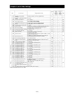
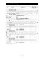
Other
s
C101
Up/Down memory mode selection
00 (not storing the frequency data), 01 (storing the frequency data)
00
¯
{
4-57
C102 Reset
mode
selection
00 (resetting the trip when RS is on),
01 (resetting the trip when RS is off),
02 (enabling resetting only upon tripping [resetting when RS is on]),
03(resetting only trip)
00
{
{
4-55
C103
Restart mode after reset
00 (starting with 0 Hz), 01 (starting with matching frequency),
02 (restarting with active matching frequency)
00
¯
{
Me
te
r
ad
justm
en
t
C105
FM gain adjustment
50. to 200. (%)
100.
{
{
4-76
C106
AM gain adjustment
50. to 200. (%)
100.
{
{
4-77
C107
AMI gain adjustment
50. to 200. (%)
100.
{
{
C109
AM bias adjustment
0. to 100. (%)
0.
{
{
C110
AMI bias adjustment
0. to 100. (%)
20.
{
{
(Note)<>indicate the setting range of 90 to 160kW
Содержание L700 Series
Страница 16: ... Memo ...
Страница 20: ... Memo ...
Страница 22: ... Memo ...
Страница 46: ... Memo ...
Страница 60: ... Memo ...
Страница 62: ... Memo ...
Страница 212: ... Memo ...
Страница 222: ... Memo ...
Страница 224: ... Memo ...
Страница 232: ... Memo ...
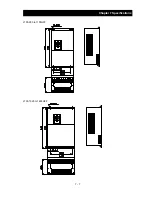
Страница 237: ...Chapter 7 Specifications 7 5 L700 300 LFF HFF L700 450 550 LFF HFF 750 HFF 5 Cable hole φ25 5 Cable hole φ41 ...
Страница 238: ...Chapter 7 Specifications 7 6 L700 750 LFF 6 Cable hole φ41 ...
Страница 239: ...Chapter 7 Specifications 7 7 L700 900 to 1100HFF L700 1320 to 1600HFF ...
Страница 240: ... Memo ...
Страница 242: ... Memo ...
Страница 258: ... Memo ...