10
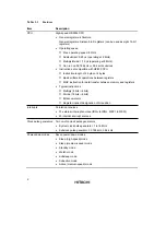
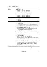
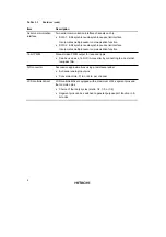
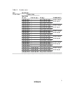
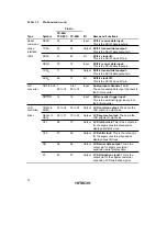
Table 1.2
Pin Functions (cont)
Pin No.
Type
Symbol
FP-80A
TFP-80C
FP-80B
I/O
Name and Functions
System
control
TEST
8
10
Output Test pin: This pin is reserved and
cannot be used. It should be connected
to V
SS
.
Interrupt
pins
IRQ
0
IRQ
1
IRQ
2
IRQ
3
IRQ
4
72
15
16
17
14
74
17
18
19
16
Input
IRQ interrupt request 0 to 4: These
are input pins for edge-sensitive
external interrupts, with a selection of
rising or falling edge
WKP
7
to
WKP
0
44 to 37
46 to 39
Input
Wakeup interrupt request 0 to 7:
These are input pins for rising or falling-
edge-sensitive external interrupts.
Timer pins
TMOW
10
12
Output Clock output: This is an output pin for
waveforms generated by the timer A
output circuit.
AEVL
AEVH
25
24
27
26
Input
Asynchronous event counter event
input: This is an event input pin for
input to the asynchronous event
counter.
TMIC
15
17
Input
Timer C event input: This is an event
input pin for input to the timer C counter.
UD
19
21
Input
Timer C up/down select: This pin
selects up- or down-counting for the
timer C counter. The counter operates
as an up-counter when this pin is high,
and as a down-counter when low.
TMIF
17
19
Input
Timer F event input: This is an event
input pin for input to the timer F counter.
TMOFL
11
13
Output Timer FL output: This is an output pin
for waveforms generated by the timer
FL output compare function.
TMOFH
12
14
Output Timer FH output: This is an output pin
for waveforms generated by the timer
FH output compare function.
TMIG
13
15
Input
Timer G capture input: This is an input
pin for timer G input capture.

