167
8.9.2
Register Configuration and Description
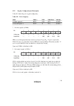
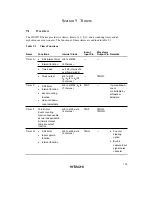
Table 8.23 shows the port A register configuration.
Table 8.23
Port A Registers
Name
Abbrev.
R/W
Initial Value
Address
Port data register A
PDRA
R/W
H'F0
H'FFDD
Port control register A
PCRA
W
H'F0
H'FFED
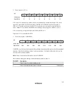
1. Port data register A (PDRA)
Bit
Initial value
Read/Write
7
—
1
—
6
—
1
—
5
—
1
—
4
—
1
—
3
PA
0
R/W
0
PA
0
R/W
2
PA
0
R/W
1
PA
0
R/W
3
2
1
0
PDRA is an 8-bit register that stores data for port A pins PA
3
to PA
0
. If port A is read while
PCRA bits are set to 1, the values stored in PDRA are read, regardless of the actual pin states. If
port A is read while PCRA bits are cleared to 0, the pin states are read.
Upon reset, PDRA is initialized to H'F0.
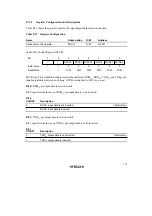
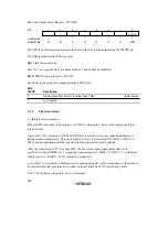
2. Port control register A (PCRA)
Bit
Initial value
Read/Write
7
—
1
—
6
—
1
—
5
—
1
—
4
—
1
—
3
PCRA
0
R/W
0
PCRA
0
R/W
2
PCRA
0
R/W
1
PCRA
0
R/W
3
2
1
0
PCRA controls whether each of port A pins PA
3
to PA
0
functions as an input pin or output pin.
Setting a PCRA bit to 1 makes the corresponding pin an output pin, while clearing the bit to 0
makes the pin an input pin. PCRA and PDRA settings are valid when the corresponding pins are
designated for general-purpose input/output by LPCR.
Upon reset, PCRA is initialized to H'F0.
PCRA is a write-only register, which always reads all 1s.


