English
12
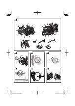
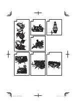
Stopping (Fig. 28)
Decrease engine speed, and push stop switch (21) to stop
position.
WARNING
Do not put the machine where there are
fl
ammable
materials such as dried grass, since the mu
ffl
er is still
hot after the engine has stopped.
Basic cutting techniques
1. Adjust the wheel guard to shield you from
fl
ying debris.
2. Cut a straight shallow line (31) to the range to be cut.
(
Fig. 29
)
3. Cut straight along the line to the required depth.
WARNING
○
Do not overreach or cut above shoulder height.
○
Operator and bystanders must not stand in the line of
rotation of the cut-o
ff
wheel. Doing so may result in serious
injury or death should the wheel burst.
○
Never apply lateral pressure (side force) to the cut-o
ff
wheel during cutting. Doing so will damage the cut-o
ff
wheel.
○
Do not cut in a curved line.
NOTE
○
When cutting, move the machine back and forward along
the line in order to be not overheat the cut-o
ff
wheel.
If you cut the same position in long time, the cut-o
ff
wheel
may get hot and be weakened.
○
Always cut at full speed at all times with pressing lightly.
This is the way to get best e
ffi
cient for cutting.
○
Do not cut a deep groove at one time. To make deep
groove, cut several times a shallow groove.
MAINTENANCE
Carburetor adjustment
In the carburetor, fuel is mixed with air. When the engine is
test run at the factory, the carburetor is adjusted. A further
adjustment may be required, according to climate and
altitude. The carburetor has one adjustment possibility:
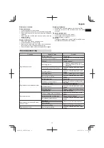
T = Idle speed adjustment screw.
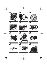
Idle speed adjustment (T) (Fig. 30)
Check that the pre-
fi
lter and paper
fi
lter are clean. When the
idle speed is correct, the cutting attachment will not rotate.
If adjustment is required, close (clockwise) the T-screw, with
the engine running, until the cutting attachment starts to
rotate. Open (counter-clockwise) the screw until the cutting
attachment stops. You have reached the correct idle speed
when the engine runs smoothly in all positions well below the
rpm when the cutting attachment starts to rotate.
If the cutting attachment still rotates after idle speed
adjustment, contact Hitachi Authorized Service Centers.
WARNING
When the engine is idling, the cutting attachment must
not rotate under any circumstances.
NOTE
○
Please use combi box spanner for adjusting the T-screw.
○
Do not touch the High speed adjustment (H) and the
Low speed adjustment (L) screws on the carburetor.
Those are only for Hitachi Authorized Service Centers.
If you rotate them, it will cause a serious damage to the
machine.
Air
fi
lter (Fig. 31)
If the engine power seems to have decreased, it is likely
because the air
fi
lter needs to be cleaned.
1. Before cleaning the air
fi
lter, pull the choke lever (22) to
prevent dust from entering into the engine.
2. Open cleaner box (B) (32) by loosening cleaner knob
(33) to expose the pre-
fi
lter (sponge form) (34) inside the
cleaner box (B) (32).
3. Clean the pre-
fi
lter by tapping or blowing it gently. If the
pre-
fi
lter is still dirty, rinse it in warm soap suds.
If the inside of cleaner box (B) (32) that is closed o
ff
by the
pre-
fi
lter is dirty with dust, clean the paper-
fi
lter (35) in the
following manner.
4. In order to take out of paper-
fi
lter (35) and nylon-
fi
lter
(36), open the cleaner box (A) (37) by loosening the M5
set bolt (38).
5. Clean the nylon-
fi
lter by tapping or blowing it gently. If
the nylon-
fi
lter is still dirty, rinse it in warm soap suds.
6. Clean the paper-
fi
lter by tapping. If you use compressed
air to blow out the dust, apply the air gently from inside.
7. Reassemble the parts to their original positions by
following the aforementioned steps in reverse.
NOTE
○
When you remove paper-
fi
lter and nylon-
fi
lter, please
take care so that dust does not get inside the engine.
○
After rinsing in warm soap suds. Check to make sure that
the
fi
lter is dry before reassembly. An air
fi
lter that has
been used for some time cannot be cleaned completely.
Therefore, it must regularly be replaced with a new one.
A
damaged
fi
lter must always be replaced.
Spark plug (Fig. 31, 32, 33)
1. Remove cleaner box (B) (32) and cleaner box (A) (37).
(
Fig. 31
)
2. Remove the spark plug by turning it counterclockwise
with the combi box spanner. (
Fig. 32
)
3. Clean the spark plug if it is dirty. Check the electrode
gap. The correct gap is 0.6 mm. (
Fig. 33
)
NOTE
○
When you remove the spark plug, please take care so
that dust does not get inside the engine.
○
The spark plug should be replaced after about 100
operation hours or earlier if the electrodes are badly
eroded.
Fuel
fi
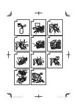
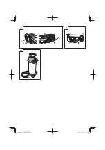
lter (Fig. 34)
Remove the fuel
fi
lter (39) from the fuel tank and thoroughly
wash it in solvent. After that, push the fuel
fi
lter into the tank
completely.
NOTE
If the fuel
fi
lter (39) is hard due to dust and dirt, it must be
replaced.
Anti-vibration systems (Fig. 35)
Check the springs (40) for any loosening or damage. If
you
fi
nd any failure in those parts, please contact a Hitachi
Authorized Service Center.
Replacing of belt
1. Remove nut (9) using the combi box spanner (6)
and loosen the tensioner bolt (11) by rotating it
counterclockwise with the hex. wrench (4). Then,
remove the arm cover (10). (
Fig. 11, 12
)
2. Loosen the three bolts (41) on the clutch cover (42) and
remove clutch cover (42). (
Fig. 36
)
3. Remove the belt (43) and set a new one in the grooves of
the pulleys (44)(45) securely. (
Fig. 37, 38
)
4. Before assembling, turn the tensioner bolt (11) and
adjust the length protrusion of the tensioner bolt (11)
from the arm cover (10) to 0 mm. (
Fig. 39
)
5. Assemble clutch cover and arm cover by following the
aforementioned steps in reverse.
6. Readjust the tension of the belt. Please refer to
“Adjustment of belt”.
0000Book̲CM75EAP.indb 12
0000Book̲CM75EAP.indb 12
2014/07/22 12:31:47
2014/07/22 12:31:47

