


48
Symptom: Keyboard produces incorrect characters or character codes
Suggested Tests:
Since the elements which determine the character codes are built into the encoder and ROM
integrated circuits at the time of manufacture, it is unlikely that they would cause transmission errors.
Much more probable is that one or more of the diodes in the memory matrix for the HERE IS sequencer
(Figure 8.13) or the three-letter sequencers (Figure 8.14) is reversed or shorted. These diodes will affect
the codes transmitted even when the sequencers are not active, since they are connected in parallel with
the ASCII output lines from the keyencoder.
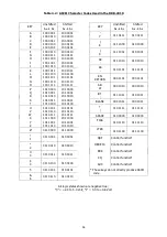
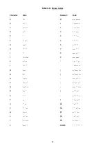
It is often possible to determine which diode is at fault by comparing the ASCII code for the character
that should be transmitted with that for the character which actually is transmitted. The ASCII codes are
given in Table 4.2.
Symptom: HERE IS sequencer or three-letter sequencer produce incorrect codes
Suggested Tests:
A common problem which may cause the automatic sequencers to produce incorrect code patterns is
improper programming (diode placement) of the memory matrix. Refer to Section V for programming
instructions. An open-circuit diode or a missing diode will also cause transmission of an incorrect code for
one character.
Symptom: Keyboard sends all dots in Morse mode and all blanks in RTTY mode
Suggested Tests:
This failure mode indicates that the data buses carrying ASCII character codes from the keyswitch
circuit board to the logic circuit board are interrupted. An improperly installed edge connector is one
possible cause; a defective or incorrectly installed buffer memory option card is another.
Symptom: One or more keys fails to produce an output
Suggested Tests:
Check for a shorted or open keyswitch. The switches must be disconnected from the circuit before
they can be checked. Rather than removing the entire keyswitch module, it is more satisfactory to break
the conductor path to the non-grounded switch terminal with a scribe. Once the switch operation has
been checked with an ohmmeter, the path may be restored by laying a small piece of bare tinned wire
across the break and soldering it in place.
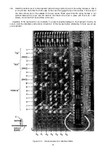
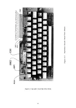
Test points for the Keyswitch circuit board and Power Supply circuit board are shown in Figures 6.2 and
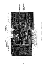
6.3, respectively. Table 6.1, located on the same fold-out as Figure 6.1, gives the location on the logic circuit
board of the many different waveforms discussed in the text. Integrated circuit designator numbers are
printed on the circuit board. Pin 1 of each IC is indicated by a "flag".
Tables 6.2 and 6.3 show the signals or voltages present at the three edge connectors. A complete wiring
list for the wire harness is presented in Table 6.4. Wire colors are assigned only for those wires that connect
to panel mounted components. Wires that only connect between circuit board edge connectors are not
assigned specific colors and are generally the same color in a given harness.
The IC pin numbers for ground and power connections are shown in Table 6.5.
Содержание DKB-2010
Страница 1: ......
Страница 20: ...18...
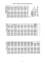
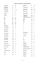
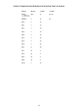
Страница 39: ...37 Table 4 3 ROM Converter Input and Output Codes...
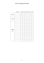
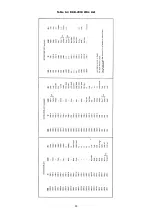
Страница 43: ...41 Table 5 1 Coding Chart for Identifier Character A0 A1 A2 A3 A4 A5 A6 CQ key AUX key HERE IS key...
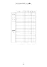
Страница 44: ...42 Table 5 1 Coding Chart for Identifier Character A0 A1 A2 A3 A4 A5 A6 CQ key AUX key HERE IS key...
Страница 52: ...50 Figure 6 1 Logic Circuit Board Test Points...
Страница 53: ...51 Figure 6 2 Keyswitch Circuit Board Test Points...
Страница 54: ...52 Figure 6 3 Power Supply Circuit Board Test Points...
Страница 57: ...55 Table 6 4 DKB 2010 Wire List...
Страница 63: ...61...
Страница 64: ...62...
Страница 65: ...63...
Страница 67: ...65...
Страница 69: ...67...
Страница 71: ...69...
Страница 73: ...71...
Страница 75: ...73...
Страница 77: ...75...
Страница 79: ...77...
Страница 81: ...79...
Страница 83: ...81...
Страница 85: ...83...
Страница 87: ...85...
Страница 89: ...87...
Страница 91: ...89...
Страница 92: ...90...
Страница 93: ...91...
Страница 94: ...92...
Страница 95: ...93...
Страница 96: ...A1 EXTENDED MEMORY OPTION FOR THE DKB 2010 KEYBOARD INSTRUCTION MANUAL...
Страница 100: ...A5...
Страница 101: ...A6...