


9
Some transmitters (such as the Yaesu FTDX-560 and several of the Swan transceivers) include a wave-
shaping filter in the key line, with a capacitor connected directly across the key terminals. The charge stored
in this capacitor can produce a current surge large enough to damage the keyboard switching transistor
when the transmitter is keyed. If such a capacitor is present in your transmitter, a resistance of between
100 and 390 ohms must be inserted in series with the line to the keyboard. Use a ½ Watt resistor, choosing
the highest value in this range that does not degrade transmitter performance. The resistor can be mounted
on the plug used to connect to the keyboard output jack.
CAUTION: HIGH VOLTAGES MAY BE PRESENT AT THE TRANSMITTER KEYING TERMINALS.
UNPLUG THE TRANSMITTER AND THE KEYBOARD BEFORE MAKING THE FOLLOWING CONNECTIONS.
For cathode keying, the keyboard output switch is connected in series with the cathode circuit of the
keyed transmitter stage. A typical installation is illustrated in Figure 2.1. Use a length of shielded wire to
connect from the transmitter to the keyboard Morse Output jack. Hook the center conductor to the cathode
of the keyed stage. Ground the shield at the transmitter. Install a plug on the other end of the cable,
connecting the center conductor to pin 3 and the shield braid to pin 2. Connect a jumper wire between pins
1 and 3 of the plug. Prepare the plug connections as shown in Figure 2.4A. Insert the plug into the Morse
Output jack on the rear panel of the keyboard.
A typical arrangement for grid-block keying is shown in Figure 2.2. In this circuit, the transistor switch
shorts the negative grid blocking voltage to ground when the transmitter is to be keyed. As in the case of
cathode keying, a shielded cable should be used to interconnect the transmitter and keyboard. At the
transmitter end, connect the center conductor to the normal keying point in the bias circuit. Ground the
shield. At the other end of the cable, install a plug with the center conductor of the cable connected to pin 1
and the shield to pin 2. Connect a jumper between pins 2 and 3 of the plug. Prepare the plug connections
as shown in Figure 2.4A. Insert the plug into the Morse output jack on the rear panel of the keyboard.
CAUTION: POTENTIALLY LETHAL VOLTAGES MAY BE PRESENT AT THE PLUG CONTACTS WHEN THE
TRANSMITTER IS TURNED ON. DO NOT DISCONNECT THE KEYING CABLE FROM THE
KEYBOARD WITHOUT FIRST SWITCHING THE TRANSMITTER OFF.
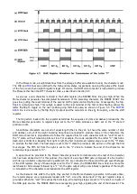
Once the keying cable has been prepared and the plug inserted into the proper keyboard jack, set the
mode switch to Morse and switch the keyboard on. Allow time for the identifier memory to clear itself; then
press any of the letter or number keys. The audio sidetone oscillator should produce the correct sequence of
dots and dashes for the character, and the transmitter should key simultaneously.
Содержание DKB-2010
Страница 1: ......
Страница 20: ...18...
Страница 39: ...37 Table 4 3 ROM Converter Input and Output Codes...
Страница 43: ...41 Table 5 1 Coding Chart for Identifier Character A0 A1 A2 A3 A4 A5 A6 CQ key AUX key HERE IS key...
Страница 44: ...42 Table 5 1 Coding Chart for Identifier Character A0 A1 A2 A3 A4 A5 A6 CQ key AUX key HERE IS key...
Страница 52: ...50 Figure 6 1 Logic Circuit Board Test Points...
Страница 53: ...51 Figure 6 2 Keyswitch Circuit Board Test Points...
Страница 54: ...52 Figure 6 3 Power Supply Circuit Board Test Points...
Страница 57: ...55 Table 6 4 DKB 2010 Wire List...
Страница 63: ...61...
Страница 64: ...62...
Страница 65: ...63...
Страница 67: ...65...
Страница 69: ...67...
Страница 71: ...69...
Страница 73: ...71...
Страница 75: ...73...
Страница 77: ...75...
Страница 79: ...77...
Страница 81: ...79...
Страница 83: ...81...
Страница 85: ...83...
Страница 87: ...85...
Страница 89: ...87...
Страница 91: ...89...
Страница 92: ...90...
Страница 93: ...91...
Страница 94: ...92...
Страница 95: ...93...
Страница 96: ...A1 EXTENDED MEMORY OPTION FOR THE DKB 2010 KEYBOARD INSTRUCTION MANUAL...
Страница 100: ...A5...
Страница 101: ...A6...