


45
VI. MAINTENANCE
When properly assembled and installed, your DKB-2010 keyboard should provide years of trouble-free
service. No routine maintenance or adjustment is required. As with any electronic device, individual
components may fail as a result of aging. The tips presented in this section will help isolate the source of
such difficulties should they occur.
The logic circuitry used in the keyboard is comparatively complex. The servicing suggestions presented
here, however, are limited to basic checks that can be made with fairly commonplace test instruments.
Unless the reader is familiar with integrated digital logic circuits and systems, it is recommended that the
more complicated service problems be referred to the factory.
Service Procedures
The DKB-2010 is constructed with high quality materials throughout. The G-10 epoxy-glass circuit boards
are used in preference to less costly materials because of their durability. Nonetheless, a reasonable amount
of care should be exercised when removing and installing components. It is particularly important that the
connections not be overheated with the soldering iron, as excessive heat may cause the printed conductors
to separate from the epoxyglass substrate. Refer to Section 5.3 for more detailed soldering instructions.
Component removal requires particular care, as it is often necessary to heat more than one pin at a time
to unsolder the component. In some cases, it may be safer to break the component and remove the pins
from the board one at a time. If this method is not practical, as in the case when the component is
expensive or a replacement is not readily available, several other techniques may be used. Specially shaped
soldering iron tips are available which allow heating all pins of a component, such as a 14-pin DIP integrated
circuit, simultaneously.
Solder wicking – essentially very fine copper braid – can be used to absorb solder from the pins once the
solder has been melted with a small iron. Touch the end of the wicking to the pin; it will draw up the excess
solder by capillary action, leaving the pin free.
The solder may also be removed by any of a variety of suction devices marketed for that purpose. All are
equipped with a rubber bulb and a tube with a solder- and heat-resistant tip. The connection is first heated
with a soldering iron. The air is expelled from the suction device by squeezing the bulb. The tip is then
placed on the connection and the bulb is released. The molten solder is carried up into the tube with the
inrush of air.
Troubleshooting
Two of the most common problems encountered with equipment constructed from kits are solder bridges
between adjacent IC pins and defects in etching resulting in shorts between adjacent conductors. In many
cases, visually inspecting the boards for such problems can save a great deal of troubleshooting time. Also,
it will pay to recheck the orientation of all integrated circuits and diodes, as it is very easy to make a mistake
during assembly.
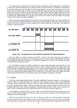
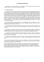
The experienced owner will find the detailed discussion of the keyboard circuitry in Section IV, "Theory of
Operation", a helpful guide to circuit performance. The waveform drawings accompanying the test should be
particularly useful for comparison to those waveforms observed in the unit under test. In the following
paragraphs, typical difficulties are listed, followed by possible causes and recommended test procedures.
CAUTION
In some of the following tests it will be necessary to operate the keyboard with the bottom
cover removed. High voltage (115 or 230 V AC) will be exposed at points within the cabinet,
particularly at the rear panel. Be extremely careful not to contact these points when making
tests.
Содержание DKB-2010
Страница 1: ......
Страница 20: ...18...
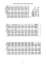
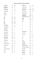
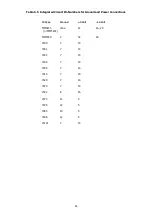
Страница 39: ...37 Table 4 3 ROM Converter Input and Output Codes...
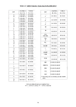
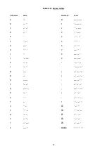
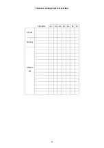
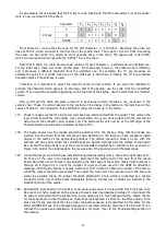
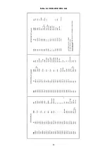
Страница 43: ...41 Table 5 1 Coding Chart for Identifier Character A0 A1 A2 A3 A4 A5 A6 CQ key AUX key HERE IS key...
Страница 44: ...42 Table 5 1 Coding Chart for Identifier Character A0 A1 A2 A3 A4 A5 A6 CQ key AUX key HERE IS key...
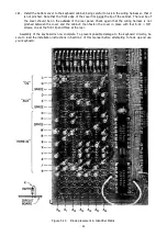
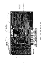
Страница 52: ...50 Figure 6 1 Logic Circuit Board Test Points...
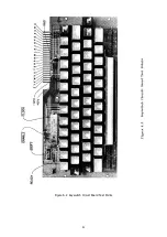
Страница 53: ...51 Figure 6 2 Keyswitch Circuit Board Test Points...
Страница 54: ...52 Figure 6 3 Power Supply Circuit Board Test Points...
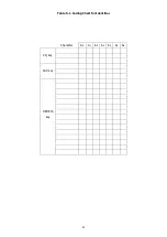
Страница 57: ...55 Table 6 4 DKB 2010 Wire List...
Страница 63: ...61...
Страница 64: ...62...
Страница 65: ...63...
Страница 67: ...65...
Страница 69: ...67...
Страница 71: ...69...
Страница 73: ...71...
Страница 75: ...73...
Страница 77: ...75...
Страница 79: ...77...
Страница 81: ...79...
Страница 83: ...81...
Страница 85: ...83...
Страница 87: ...85...
Страница 89: ...87...
Страница 91: ...89...
Страница 92: ...90...
Страница 93: ...91...
Страница 94: ...92...
Страница 95: ...93...
Страница 96: ...A1 EXTENDED MEMORY OPTION FOR THE DKB 2010 KEYBOARD INSTRUCTION MANUAL...
Страница 100: ...A5...
Страница 101: ...A6...