


24
In the Morse mode, all eight data lines from the storage buffer are available to carry the character code.
The M/R and
M/R
lines are switched to the high and low states, respectively, opening the gates at the inputs
of the first, seventh and eighth register stages. Of course, the ROM code converter is instructed to produce
the Morse rather than the RTTY character code, as described in Section 4.5.
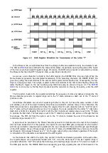
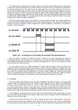
As soon as a new character is stored in the buffer register, the BUFFER FULL line goes high. When the
Morse character generator has completed transmission of the preceding character, the MORSE START line
goes low, pulling the reset terminal of the second shift register control flip-flop low. Consequently, the flip-
flop's
Q
output goes high. This output, coupled to the clear terminal of the first control flip-flop, allows the
latter flip-flop to toggle on the next positive-going HØ clock pulse, as shown in Figure 4.3. The
BUFFER
READ
line is driven low by the flip-flop's Q output and the code bits on lines D
0
through D
7
enter the shift
register.
The bit pattern loaded into the register determines the sequence of dots and dashes produced by the
Morse character generator. A register stage set to the "0" state produces a dash; set to the "1" state it
produces a dot.
Since Morse characters are not all of equal length (that is, they do not have the same number of dots
and dashes), not all of the eight incoming data lines are needed to produce many of the characters. the
ROM code converter is programmed to follow the required bits for each character with an "end" bit set to
the "l" state, with all remaining bits set low. For example, the code supplied for the letter "C" (dash-dot-
dash-dot) is 00011010, Reading from right to left, the first (right-most) register stage is set to the "0" state
to produce the first dash. The next stage is set to the "l" state to produce a dot, and so on through the first
four stages. The fifth bit from the right is set to the "1" state to indicate the end of the character. All
remaining stages are set to "0".
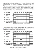
A signal must be provided to the Morse character generator to indicate when the last of the character
bits has been clocked out. For this purpose, the inputs of a six-input NOR gate, composed of a hex inverter
with its open-collector outputs wired in parallel (IC-17), are connected to the second through seventh stages
of the shift register. If any of these stages is set to the "1" state, the MORSE END line is held low. Since the
last character bit is always followed by a "1" bit, the gate output will go low initially regardless of the length
or bit pattern of the character code loaded into the shift register.
As the character bits shift to the right, they are fed to the Morse character generator. At the same time,
the register stages are progressively loaded with "0's", since the data input of the last register stage is
grounded. When the "end" bit reaches the first stage, all remaining stages are set to "0" and all six inputs of
the NOR gate are low. The MORSE END line consequently goes high, signaling the end of the character. The
Содержание DKB-2010
Страница 1: ......
Страница 20: ...18...
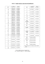
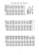
Страница 39: ...37 Table 4 3 ROM Converter Input and Output Codes...
Страница 43: ...41 Table 5 1 Coding Chart for Identifier Character A0 A1 A2 A3 A4 A5 A6 CQ key AUX key HERE IS key...
Страница 44: ...42 Table 5 1 Coding Chart for Identifier Character A0 A1 A2 A3 A4 A5 A6 CQ key AUX key HERE IS key...
Страница 52: ...50 Figure 6 1 Logic Circuit Board Test Points...
Страница 53: ...51 Figure 6 2 Keyswitch Circuit Board Test Points...
Страница 54: ...52 Figure 6 3 Power Supply Circuit Board Test Points...
Страница 57: ...55 Table 6 4 DKB 2010 Wire List...
Страница 63: ...61...
Страница 64: ...62...
Страница 65: ...63...
Страница 67: ...65...
Страница 69: ...67...
Страница 71: ...69...
Страница 73: ...71...
Страница 75: ...73...
Страница 77: ...75...
Страница 79: ...77...
Страница 81: ...79...
Страница 83: ...81...
Страница 85: ...83...
Страница 87: ...85...
Страница 89: ...87...
Страница 91: ...89...
Страница 92: ...90...
Страница 93: ...91...
Страница 94: ...92...
Страница 95: ...93...
Страница 96: ...A1 EXTENDED MEMORY OPTION FOR THE DKB 2010 KEYBOARD INSTRUCTION MANUAL...
Страница 100: ...A5...
Страница 101: ...A6...