


44
181. Install the bottom cover to the keyboard cabinet, being careful to tuck in the wiring harness so that it
is not pinched. Note that the front edge of the cover fits inside the lip of the cabinet. The rear lip of
the cover should be on the outside of the rear panel. Check again that the wiring harness is not
pinched between the cover and the cabinet; then fasten the cover in place with four 6-32 × 5/6"
screws, one at the front lip and three at the rear.
Assembly of the keyboard is now complete. To prevent possible damage to the keyboard circuitry, be
sure to read the installation instructions in Section 2 of this manual before attempting to hook up and use
your keyboard.
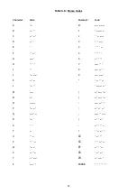
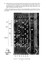
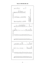
Figure 5.14 Diode placement in Identifier Matrix
Содержание DKB-2010
Страница 1: ......
Страница 20: ...18...
Страница 39: ...37 Table 4 3 ROM Converter Input and Output Codes...
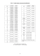
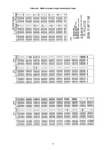
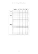
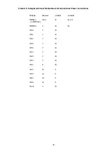
Страница 43: ...41 Table 5 1 Coding Chart for Identifier Character A0 A1 A2 A3 A4 A5 A6 CQ key AUX key HERE IS key...
Страница 44: ...42 Table 5 1 Coding Chart for Identifier Character A0 A1 A2 A3 A4 A5 A6 CQ key AUX key HERE IS key...
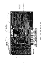
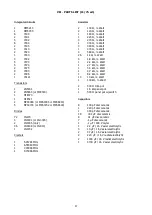
Страница 52: ...50 Figure 6 1 Logic Circuit Board Test Points...
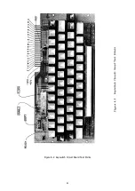
Страница 53: ...51 Figure 6 2 Keyswitch Circuit Board Test Points...
Страница 54: ...52 Figure 6 3 Power Supply Circuit Board Test Points...
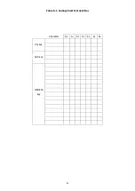
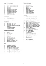
Страница 57: ...55 Table 6 4 DKB 2010 Wire List...
Страница 63: ...61...
Страница 64: ...62...
Страница 65: ...63...
Страница 67: ...65...
Страница 69: ...67...
Страница 71: ...69...
Страница 73: ...71...
Страница 75: ...73...
Страница 77: ...75...
Страница 79: ...77...
Страница 81: ...79...
Страница 83: ...81...
Страница 85: ...83...
Страница 87: ...85...
Страница 89: ...87...
Страница 91: ...89...
Страница 92: ...90...
Страница 93: ...91...
Страница 94: ...92...
Страница 95: ...93...
Страница 96: ...A1 EXTENDED MEMORY OPTION FOR THE DKB 2010 KEYBOARD INSTRUCTION MANUAL...
Страница 100: ...A5...
Страница 101: ...A6...