


19
4.4 Scanning Keyboard Encoder
The transmission of individual characters is initiated by the keyboard encoder section. An integrated
circuit keyencoder, in conjunction with a matrix of 46 keyswitches, produces an ASCII code output for each
key closure.
The encoder and keyswitch matrix are shown in Figure 8.3. Each keyswitch is represented by a box in
the larger rectangle at the left. The rows and columns of the matrix are formed by buses connected to the X
and Y terminals of the encoder IC. Any keyswitch, when closed, completes the circuit between one of the X
(row) and Y (column) terminals. Thus each keyswitch is assigned a unique pair of x,y coordinates in the
matrix.
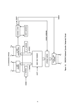
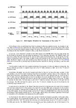
A block diagram of the encoder IC is shown in Figure 4.1. A dynamic scanning method is used to sense
the closure of keyswitches and to produce the required ASCII output code for the corresponding characters.
Clock pulses, supplied from the RTTY timing chain (described in Section 4.10), drive the X counter in the IC.
As the counter increments, the X (row) lines of the matrix are driven high sequentially.
The Y counter, which increments once for each complete cycle of the X counter, causes the Y (column)
sense lines to be monitored in sequence. If a keyswitch is closed, connecting one of the X lines to one of the
Y lines, the closure will be detected by the key sense logic circuit when that particular X line is driven high
and the Y Line is simultaneously sensed. The state of the counters at the instant the keyclosure is detected
then corresponds to the X and Y coordinates of the closed key.
The encoder IC includes a read-only memory (ROM) to convert the coordinates supplied by the counters
to the correct ASCII code for the character. Each location in the memory stores the ASCII code for one of
the 46 characters
. As the X and Y counters increment, they not only enable the X and Y matrix lines, but
also provide an address code to the ROM. Thus the memory locations are addressed in sequence as the key
matrix is scanned, and the ASCII codes for each of the keyswitches appear in sequence at the ROM output.
As long as the keyswitches remain open, the output of the ROM is ignored. If, however, during the scanning
process a closed keyswitch is detected, the key sense logic causes the code appearing at the ROM output at
that instant to be transferred to the storage buffer.
The scanning process is dynamic; that is, the counters are cycled repetitively at a fairly high rate, so that
key closures are detected almost instantly.
Some of the keys can produce two different characters, a shifted and an unshifted one. The character
produced by such a key depends on whether one of the shift keyswitches is closed. If it is, it alters one bit
of the address fed to the ROM, thereby accessing a different storage location and producing a different
output code.
An important and useful feature of the encoder is the provision for N-key rollover, which is defined as the
ability to produce an output code each time a new key is pressed without regard to the condition of the
other keyswitches. In practical terms, it means that new key closures will be detected even if the operator
has failed to release preceding keys.
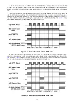
During each scan of the key matrix, the output of the sensing circuitry is fed in serial form to a shift
register. Once the scan is complete, the register contains a digital "list" of the status of all keyswitches.
During the next scan, the register contents are clocked out as the new data are fed in. The register's input
and output are compared; if any of the keys have changed state between the scans, the difference will be
detected. The control logic then recognizes the new key closure as valid and allows the ROM output code
(for the new key only) to enter the storage buffer. Keys which were closed on both scans have no effect on
the output, since no change in their state is detected.
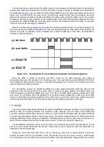
When a character has been stored in the buffer and is ready for transfer to the keyboard's code
conversion circuit, a data strobe signal (logic high level) appears at pin 13. This strobe drives the keyboard
READY bus, signaling the keyboard buffer control circuit that a character is waiting in the encoder's output
storage register. This strobe signal also feeds a lamp driver, causing the "memory full" lamp, ID101, to light.
When the keyboard control circuit is ready to accept the waiting character, it returns a signal on the
ENABLE
line, causing the encoder IC's data drivers to transmit the stored character to the keyboard's code
Содержание DKB-2010
Страница 1: ......
Страница 20: ...18...
Страница 39: ...37 Table 4 3 ROM Converter Input and Output Codes...
Страница 43: ...41 Table 5 1 Coding Chart for Identifier Character A0 A1 A2 A3 A4 A5 A6 CQ key AUX key HERE IS key...
Страница 44: ...42 Table 5 1 Coding Chart for Identifier Character A0 A1 A2 A3 A4 A5 A6 CQ key AUX key HERE IS key...
Страница 52: ...50 Figure 6 1 Logic Circuit Board Test Points...
Страница 53: ...51 Figure 6 2 Keyswitch Circuit Board Test Points...
Страница 54: ...52 Figure 6 3 Power Supply Circuit Board Test Points...
Страница 57: ...55 Table 6 4 DKB 2010 Wire List...
Страница 63: ...61...
Страница 64: ...62...
Страница 65: ...63...
Страница 67: ...65...
Страница 69: ...67...
Страница 71: ...69...
Страница 73: ...71...
Страница 75: ...73...
Страница 77: ...75...
Страница 79: ...77...
Страница 81: ...79...
Страница 83: ...81...
Страница 85: ...83...
Страница 87: ...85...
Страница 89: ...87...
Страница 91: ...89...
Страница 92: ...90...
Страница 93: ...91...
Страница 94: ...92...
Страница 95: ...93...
Страница 96: ...A1 EXTENDED MEMORY OPTION FOR THE DKB 2010 KEYBOARD INSTRUCTION MANUAL...
Страница 100: ...A5...
Страница 101: ...A6...