


8
II. INSTALLATION
2.1 Initial Inspection
When you unpack your DKB-2010 keyboard, examine it carefully. If evidence of shipping damage is
found, contact the carrier immediately. Before discarding the packing material, check that all parts and
accessories are accounted for (included accessories are listed in Section 1.3). If any are missing, please
notify the factory in writing.
If your keyboard is in kit form, check the parts against the list in Section 7 of this manual. Then turn to
Section 5 for assembly instructions.
2.2 Preliminary Checkout
Connect the power cord to an AC source of the proper voltage and frequency.
NOTE: The keyboard can be connected for either 105 to 125 volt or 210 to 250 volt operation. Factory-
assembled units are wired for nominal 115 volt input unless otherwise indicated by a tag attached to
the power cord. Before connecting the power cord, be certain that the voltage of the outlet
corresponds to the keyboard input voltage rating.
To ensure operator safety, connect the power cord to a three-prong outlet with safety ground. DO NOT
attempt to defeat the grounding prong of the keyboard cordset. To do so will void the warranty.
Next, rotate the mode switch to the Morse position. Switch the keyboard on by rotating the volume
control clockwise to about the center of its range. When power is first applied, the identifier and the three-
character memory circuits may be in their active states. If so, the stored characters will be clocked out of
the memory in rapid succession. Wait until the process is complete. Then press any of the letter or number
keys. The keyboard should produce a keyed audio tone corresponding to the Morse code pattern of dots and
dashes for the character. Test several other keys, adjusting the speed, volume, and weight controls to check
their operation. If this preliminary test is satisfactory, the keyboard is ready to be connected to your CW
transmitter and RTTY loop circuit.
If the keyboard will be used for both RTTY and Morse operation in your station, prepare the connecting
cables described in Sections 2.3 and 2.4. The keyboard may be left connected to both the RTTY loop and
the CW transmitter; it is not necessary to exchange cables or remove plugs when changing modes, as the
RTTY and Morse output stages of the keyboard are completely independent. Of course, the keyboard need
not be used for both modes. In that case, simply prepare cables for the appropriate output Jacks and leave
the others unconnected.
BEFORE PROCEEDING WITH THE INSTALLATION, DISCONNECT THE AC POWER CORD.
2.3 CW Transmitter Keying Connections
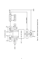
The keyboard Morse output stage is a high-voltage switching transistor. When connected to the
transmitter, this electronic switch takes the place of the normal hand key. The keyboard may be connected
for either cathode or grid-block keying (but not both at the same time), depending on which of the two
rear-panel keying jacks is used. The two Morse output connections may not be used at the same time. The
Morse output control circuitry is shown in Figure No. 8.11.
Before attempting to connect the keyboard to the transmitter keying terminals, examine the transmitter
circuit diagram carefully to determine the keying method used. The keyboard cannot be used with "floating"
key circuits; one of the two keying terminals must be grounded within the transmitter.
The transistor keying switch is rated to withstand 250 volts at up to 150 mA in cathode keying service.
For grid-block keying, the voltage at the key should not exceed -150 volts, and the current should not be
greater than 150 mA. Before connecting the keyboard, measure the voltage across the keying terminals of
the transmitter with the key open and the current through the key when it is closed to ensure that these
ratings are not exceeded.
Содержание DKB-2010
Страница 1: ......
Страница 20: ...18...
Страница 39: ...37 Table 4 3 ROM Converter Input and Output Codes...
Страница 43: ...41 Table 5 1 Coding Chart for Identifier Character A0 A1 A2 A3 A4 A5 A6 CQ key AUX key HERE IS key...
Страница 44: ...42 Table 5 1 Coding Chart for Identifier Character A0 A1 A2 A3 A4 A5 A6 CQ key AUX key HERE IS key...
Страница 52: ...50 Figure 6 1 Logic Circuit Board Test Points...
Страница 53: ...51 Figure 6 2 Keyswitch Circuit Board Test Points...
Страница 54: ...52 Figure 6 3 Power Supply Circuit Board Test Points...
Страница 57: ...55 Table 6 4 DKB 2010 Wire List...
Страница 63: ...61...
Страница 64: ...62...
Страница 65: ...63...
Страница 67: ...65...
Страница 69: ...67...
Страница 71: ...69...
Страница 73: ...71...
Страница 75: ...73...
Страница 77: ...75...
Страница 79: ...77...
Страница 81: ...79...
Страница 83: ...81...
Страница 85: ...83...
Страница 87: ...85...
Страница 89: ...87...
Страница 91: ...89...
Страница 92: ...90...
Страница 93: ...91...
Страница 94: ...92...
Страница 95: ...93...
Страница 96: ...A1 EXTENDED MEMORY OPTION FOR THE DKB 2010 KEYBOARD INSTRUCTION MANUAL...
Страница 100: ...A5...
Страница 101: ...A6...