


35
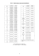
4.18 Character Codes
The tables on the following pages list the various character codes used in the DKB-2010 keyboard.
Table 4.2 tabulates that portion of the ASCII character set produced by the keyencoder circuit. Only
those ASCII characters which correspond to Military Standard Baudot characters are used. The codes, which
appear at the keyencoder output on data lines A
0
through A
6
, are listed in the table opposite the characters
they represent. The A
6
bit is listed first, followed by the other bits in descending order, with the bit for line
A
0
at the right. Note that the keyencoder output logic is negative true; that is, a "1" represents a low level
(less than 0.8 Volt), and a "0" represents a high level (from 2.4 to 5.0 Volt).
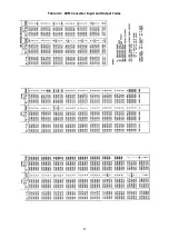
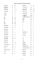
As discussed in Section 4.5, the ASCII code is converted by a ROM to a different bit pattern before being
loaded into the shift register. The ROM output, which appears on lines D
0
through D
7
, is listed in Table 4.3
along with the character each code represents and with the corresponding ASCII input code. The ROM
produces different outputs for Morse and RTTY modes, depending on the state of the A
7
input bit. Both
output codes are listed for each character. Since some of the characters are not available in the Morse
mode, the output bits for such characters consist entirely of "0's". The bits are listed in descending order,
with the D
7
bit at the left. As in the ASCII code listing, the logic is negative true.
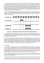
Table 4.4 lists the Military Standard Baudot code produced by the keyboard in the RTTY mode. The code
for each RTTY character is made up of seven bits – a start pulse, five character-defining select pulses and a
stop pulse. Since the start bit is always a space and the stop bit is always a mark, they are not shown in the
table, only the five select pulses are listed. Note that the same code may be used to produce two different
characters, depending on the case to which the receiving teleprinter is set – letters or figures.
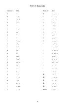
In Table 4.5 the keyboard output codes for each of the Morse characters is listed. In comparing these
codes to the ROM code converter output bits, recall that the ROM is programmed to include an extra dot bit
at the end of each character for generation of the intercharacter space.
Содержание DKB-2010
Страница 1: ......
Страница 20: ...18...
Страница 39: ...37 Table 4 3 ROM Converter Input and Output Codes...
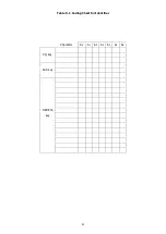
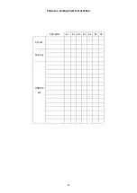
Страница 43: ...41 Table 5 1 Coding Chart for Identifier Character A0 A1 A2 A3 A4 A5 A6 CQ key AUX key HERE IS key...
Страница 44: ...42 Table 5 1 Coding Chart for Identifier Character A0 A1 A2 A3 A4 A5 A6 CQ key AUX key HERE IS key...
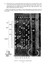
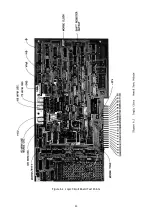
Страница 52: ...50 Figure 6 1 Logic Circuit Board Test Points...
Страница 53: ...51 Figure 6 2 Keyswitch Circuit Board Test Points...
Страница 54: ...52 Figure 6 3 Power Supply Circuit Board Test Points...
Страница 57: ...55 Table 6 4 DKB 2010 Wire List...
Страница 63: ...61...
Страница 64: ...62...
Страница 65: ...63...
Страница 67: ...65...
Страница 69: ...67...
Страница 71: ...69...
Страница 73: ...71...
Страница 75: ...73...
Страница 77: ...75...
Страница 79: ...77...
Страница 81: ...79...
Страница 83: ...81...
Страница 85: ...83...
Страница 87: ...85...
Страница 89: ...87...
Страница 91: ...89...
Страница 92: ...90...
Страница 93: ...91...
Страница 94: ...92...
Страница 95: ...93...
Страница 96: ...A1 EXTENDED MEMORY OPTION FOR THE DKB 2010 KEYBOARD INSTRUCTION MANUAL...
Страница 100: ...A5...
Страница 101: ...A6...