44
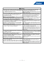
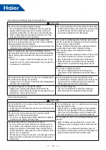
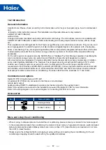
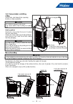
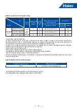
(1) Installation place selection
Air-conditioner can't be installed in
the place with inflammable gas. Or it
will cause fire hazard.
The unit should be installed at the
place with good ventilation. No
obstacle at the air inlet/outlet. And no
strong wind blows the unit.
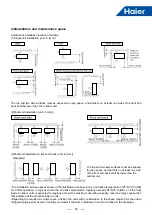
The installation space refers to the
latter info.
The unit should be installed at the
strong enough place. Or it will cause
vibration and noise.
The unit should be installed at the
place where the cold/hot air or noise
will not interfere the neighbours.
•The place where the water can flow
fluently.
•The place where no other heat
source will affect the unit.
•Pay attention to the snow against
clogging the outdoor.
•In installation, install the anti-
vibration rubber between the unit and
the bracket.
•The unit is better not be installed
at the below places, or it will cause
damage.
•The place where there is corrosive
gas (spa area etc).
•The place blowing salty air (seaside
etc).
•Exsits the strong coal smoke.
•The place with high humidity.
•The place where there is device
emitting Hertzian waves.
•The place where voltage changes
greatly
Note:
1.In snowy area, install the unit under the bracket or the snow-proof cover against the accumulative snow on the
unit.
2.Do not install the unit at the place where the flammable gas will leak.
3.Install the unit at the strong enough place.
4.Install the unit at the flat place.
5.When being installed at the place with strong wind, set the air outlet of the unit and the wind direction vertical.
6.The installation site should be far away from the place where the noise is higher. At the same time for the noise of
higher places should ensure that the outdoor machine vibration and wall insulation measures to prevent vibration
caused by thin wall or acoustic noise problems.
7.Aluminum foil fin is very sharp, pay attention to prevent scratches.
8.In addition to the maintenance of the roof, or the installation of outdoor machines, other people can not contact
the outdoor machine.
14.4 Installation instruction
Содержание AU082FYCRA(HW)
Страница 1: ...ATW Service Manual SYJS 03 2019REV A Edition 2019 03 ...
Страница 11: ...9 405 410 600 174 174 450 950 965 395 6 Dimensions AU082FYCRA HW Unit mm ...
Страница 12: ...10 AU112 162FYCRA HW Unit mm 1490 950 380 187 405 410 600 174 174 450 170 ...
Страница 13: ...11 AU082FYCRA HW 7 Piping Diagram ...
Страница 14: ...12 AU112 162FYCRA HW ...
Страница 27: ...25 12 Water Pressure Drop ...
Страница 28: ...26 ...
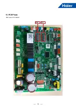
Страница 57: ...55 15 PCB Photo BM2 BM1 PCB code 0151800423 ...

