Test Operation & Troubleshooting & Maintenance
Note:
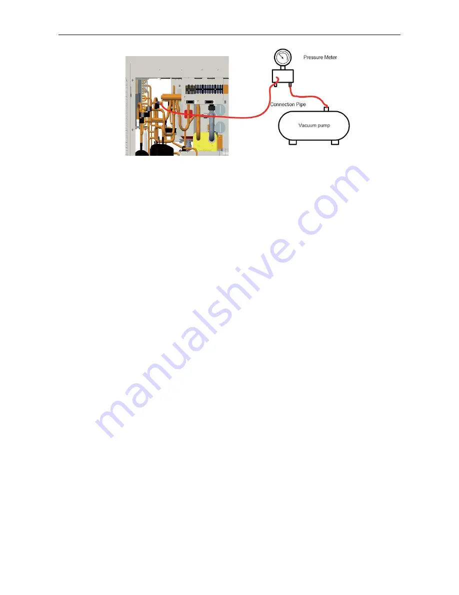
when vacuuming is finished, pressure inside the unit should be kept lower than 80Pa for at least 30
minutes to make sure there is no leak. Either charging valve 1 or charging valve 2 can be used for
vacuuming.
Charging:
when vacuuming is finished and it is certain that there is no leak, charging can be done.
Leak Detection Methods
:
The following leak detection methods are deemed acceptable for systems containing flammable
refrigerants.
Electronic leak detector shall be used to detect flammable refrigerant, but the sensitivity may not be
adequate, or may need re-calibration(Detection equipment shall be calibrated in a refrigerant-free area).
Ensure that the detector is not a potential source of ignition and is suitable for the refrigerant used.
Leak detection equipment shall be set at a percentage of the LFL of the refrigerant and shall be
calibrated to the refrigerant employed and the appropriate percentage of gas (25% maximum) is
confirmed.
Leak detection fluids are suitable for us with most refrigerant but the use of detergents containing
chlorine shall be avoided as the chlorine may react with the refrigerant and corrode the copper
pipe-work.
If a leak is suspected, all naked flames shall be removed / extinguished. If a leakage of refrigerant is
found which requires brazing, all of the refrigerant shall be recovered from the system, or isolated (by
means of shut off valves) in a part of the system remote from the leak. Oxygen free nitrogen (OFN) shall
then be purged through the system both before and during the brazing process.
Note:
Before and during operation, use an appropriate refrigerant leak detector to monitor the operation area
and make sure the technicians can be well aware of any potential or actual leakage of inflammable gas.
Make sure the leak detecting device is applicable to inflammable refrigerant. For example, it should be
free of sparks, completely sealed and safe in nature.
Содержание VERSATI III Series
Страница 1: ...VERSATI Ⅲ Air To Water Heat Pump ...
Страница 5: ...Engineering Data ENGINEERING DATA ...
Страница 10: ...Engineering Data 1 4 Operating Principle 1 4 1 Schematic Diagram ...
Страница 22: ...Design and Selection DESIGN SELECTION ...
Страница 33: ...Unit Control UNIT CONTROL ...
Страница 72: ...Unit Control ...
Страница 76: ...Unit Control 3 3 2 Setting of Main Functions 1 Set mode and temperature ...
Страница 77: ...Unit Control 2 Click Func at the left lower corner in device operation interface to enter advanced settings ...
Страница 79: ...Unit Control 3 3 3 2 Help Click Help and view the operation instructions of the APP ...
Страница 80: ...Unit Control ...
Страница 81: ...Unit Control 3 3 3 3 Feedback Click Feedback to submit feedback ...
Страница 82: ...Installation UNIT INSTALLATION ...
Страница 113: ...Test Operation Troubleshooting Maintenance TEST OPERATION TROUBLESHOOTING MAINTENANCE ...
Страница 117: ...Test Operation Troubleshooting Maintenance 3 Flow Chart of Troubleshooting 3 1 Comp High pressure Protection E1 ...
Страница 118: ...Test Operation Troubleshooting Maintenance 3 2 Comp Low pressure Protection E3 ...
Страница 119: ...Test Operation Troubleshooting Maintenance 3 3 Comp Discharge Temp Protection E4 ...
Страница 120: ...Test Operation Troubleshooting Maintenance 3 4 Overload Protection of Compressor or Driver Error ...
Страница 121: ...Test Operation Troubleshooting Maintenance 3 5 DC Fan Error EF 3 6 Temperature Sensor Error ...
Страница 122: ...Test Operation Troubleshooting Maintenance 3 7 Communication Malfunction E6 ...
Страница 123: ...Test Operation Troubleshooting Maintenance 3 8 Capacity Switch Error Code C5 ...
Страница 125: ...Test Operation Troubleshooting Maintenance IPM or PFC Over temperature Protection Code P8 ...
Страница 127: ...Test Operation Troubleshooting Maintenance ...
Страница 135: ...Test Operation Troubleshooting Maintenance ...


