3
FinePix S602 ZOOM SERVICE MANUAL
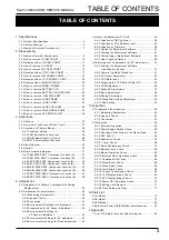
TABLE OF CONTENTS
TABLE OF CONTENTS
1.Specifications
1-1.Product Specifications ....................................................... 4
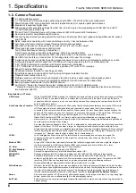
1-2.Camera Features ................................................................ 6
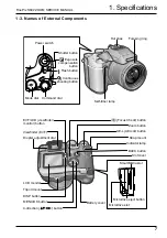
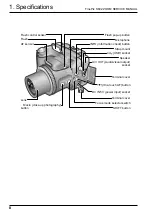
1-3.Names of External Components ...................................... 7
2.Disassembly
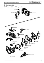
2-1.Names of Internal Components ....................................... 9
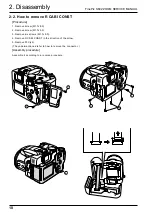
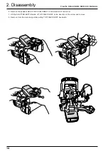
2-2.How to remove R CABI CONST .................................... 10
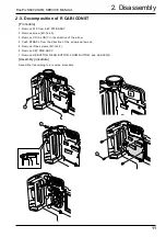
2-3.Decomposition of R CABI CONST ................................ 11
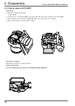
2-4.How to remove LCD ASSY ............................................ 12
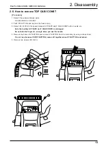
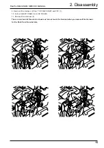
2-5.How to remove TOP CABI CONST ............................... 13
2-6.Decomposition of TOP CABI CONST .......................... 17
2-7.How to remove LCD FRAME CONST ........................... 19
2-8.Decomposition of LCD FRAME CONST ...................... 20
2-9.Decomposition of MAIN PWB ASY ............................... 20
2-10.How to remove SHEET FRAME .................................. 21
2-11.How to remove BATTERY LID .................................... 21
2-12.How to remove BATTERY HOLDER UNIT ................ 22
2-13.How to remove CAM PWB ASSY ............................... 22
2-14.How to remove LENS FRAME ..................................... 23
2-15.How to remove LENS CONST ..................................... 23
2-16.How to remove LENS CABI ASSY ............................. 24
2-17.How to remove SIDE MODULE UNIT ........................ 25
2-18.How to remove AF SENSOR UNIT ............................. 26
3.Schematic
3-1.Cautions ............................................................................ 27
3-2.Overview of Functions of Each Circuit ......................... 27
3-3.Functions of Primary Blocks .......................................... 28
3-4.Block Diagram ................................................................. 29
3-5.Overall ............................................................................... 30
3-6.Board mounting diagram ................................................ 31
3-6-1.CAM PWB ASSY Component Location (A) .......... 31
3-6-2.CAM PWB ASSY Component Location (B) .......... 32
3-6-3.KEY PWB ASSY Component Location (A) .......... 33
3-6-4.KEY PWB ASSY Component Location (B) .......... 34
3-6-5.MAIN PWB ASSY Component Location (A) ........ 35
3-6-6.MAIN PWB ASSY Component Location (B) ........ 36
3-6-7.DCST PWB ASSY Component Location (A) ........ 37
3-6-8.DCST PWB ASSY Component Location (B) ........ 38
4.Adjustment
4-1.Adjustments to Primary Components Following
Replacement ................................................................... 39
4-2.Preparation for adjustments .......................................... 40
4-2-1.Measuring Equipments ............................................ 40
4-2-2.Jigs and Charts ........................................................ 40
4-2-3.Connection ................................................................ 41
4-2-4.Environmental Settings for Adjustment ................ 42
4-2-5.Preparations for AF Sensor Adjustment ............... 42
4-2-6.Environmental Settings for
AF Sensor Adjustment ........................................... 42
4-3.About the Adjustment PC Soft ...................................... 44
4-3-1.Attention at DSC jig driver ...................................... 44
4-3-2.Attention at PC adjustment soft ............................. 45
4-3-3.Attention at Firmware .............................................. 46
4-3-4.Content of Adjustment Software ............................ 47
4-3-5.Starting the Adjustment Software .......................... 47
4-3-6.Customizing of Adjustment Software .................... 48
4-3-7.Use of each command ............................................ 50
4-4.Adjustment of Components (for PC adjustment) ........ 51
4-4-1.Starting the Adjustment Software
(cautions during use) .............................................. 51
4-4-2.Camera Jig Mode Procedure .................................. 51
4-4-3.AF Sensor Adjustment ............................................ 52
4-4-4.CCD Data Input ........................................................ 54
4-4-5.Preparing the CCD Defect Data (FD) ................... 55
4-4-6.CAM Adjustment ...................................................... 56
4-4-7.Zoom/AF Adjustment ............................................... 57
4-4-8.Flash Adjustment ..................................................... 58
4-4-9.Battery Adjustment .................................................. 59
4-4-10.Mode Dial Voltage Adjustment ............................ 60
4-4-11.End Setting ............................................................. 61
5.Inspection
5-1.Preparation for inspection .............................................. 62
5-1-1.Measuring Equipments ............................................ 62
5-1-2.Jigs and Charts ........................................................ 62
5-1-3.Connection ................................................................ 63
5-2.Inspection ......................................................................... 64
5-2-1.External Inspection .................................................. 64
5-2-2.Power Supply Switch Check ................................... 64
5-2-3.Checking Shock Noise in the Movie Mode ........... 64
5-2-4.EVF Check ................................................................ 64
5-2-5.Resolution Check ..................................................... 65
5-2-6.Y Level Check .......................................................... 66
5-2-7.Flash Photography Check ...................................... 67
5-2-8.Manual Focus Check ............................................... 68
5-2-9.Macro Operation Check .......................................... 68
5-2-10.External Flash Operation Check .......................... 68
5-2-11.Command Dial Check ........................................... 68
5-2-12.Movie/Audio Check ................................................ 68
5-2-13.Erase Mode Check ................................................ 68
5-2-14.Low Battery Check ................................................. 69
5-2-15.Current Consumption Check ................................ 69
5-2-16.LCD Display Image Check ................................... 69
5-2-17.EVF Display Image Check .................................... 70
5-2-18.Power OFF Operation Check ............................... 70
5-2-19.Settings at Shipment ............................................. 71
5-2-20.Clock Setup and Clear .......................................... 71
6.Parts List
6-1.U-Model ............................................................................ 72
6-2.E-Model ............................................................................. 77
6-3.EG-Model .......................................................................... 82
6-4.Electrical Parts (U/E/EG-Model commonness) ........... 87
7.Appendix
7-1.List of Related Technical Updates Issued ................... 88

