


MPC5553/MPC5554 Microcontroller Reference Manual, Rev. 5
Freescale Semiconductor
20-61
minimum of 2 system clocks. Refer to
Section 20.3.2.3, “DSPI Clock and Transfer Attributes Registers
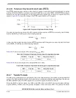
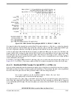
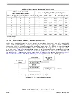
Figure 20-42. Polarity Switching between Frames
20.4.8
Continuous Serial Communications Clock
The DSPI provides the option of generating a continuous SCK signal for slave peripherals that require a
continuous clock.
Continuous SCK is enabled by setting the CONT_SCKE bit in the DSPI
x
_MCR. Continuous SCK is valid
in all configurations.
Continuous SCK is only supported for CPHA = 1. Setting CPHA = 0 will be ignored if the CONT_SCKE
bit is set. Continuous SCK is supported for modified transfer format.
Clock and transfer attributes for the continuous SCK mode are set according to the following rules:
•
When the DSPI is in SPI configuration, CTAR0 shall be used initially. At the start of each SPI
frame transfer, the CTAR specified by the CTAS for the frame shall be used.
•
When the DSPI is in DSI configuration, the CTAR specified by the DSICTAS field shall be used
at all times.
•
When the DSPI is in CSI configuration, the CTAR selected by the DSICTAS field shall be used
initially. At the start of an SPI frame transfer, the CTAR specified by the CTAS value for the frame
shall be used. At the start of a DSI frame transfer, the CTAR specified by the DSICTAS field shall
be used.
•
In all configurations, the currently selected CTAR shall remain in use until the start of a frame with
a different CTAR specified, or the continuous SCK mode is terminated.
It is recommended that the baud rate is the same for all transfers made while using the continuous SCK.
Switching clock polarity between frames while using continuous SCK can cause errors in the transfer.
Continuous SCK operation is not guaranteed if the DSPI is put into module disable mode.
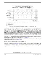
Enabling continuous SCK disables the PCS to SCK delay and the After SCK delay. The delay after transfer
is fixed at one SCK cycle.
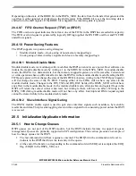
shows timing diagram for continuous SCK format with continuous
selection disabled.
PCS
System Clock
SCK
Frame 1
Frame 0
CPOL = 0
CPOL = 1
A
B
Содержание MPC5553
Страница 5: ...MPC5553 MPC5554 Microcontroller Reference Manual Rev 5 2 Freescale Semiconductor...
Страница 21: ...MPC5553 MPC5554 Microcontroller Reference Manual Rev 5 xvi Freescale Semiconductor...
Страница 47: ...MPC5553 MPC5554 Microcontroller Reference Manual Rev 5 1 26 Freescale Semiconductor...
Страница 163: ...MPC5553 MPC5554 Microcontroller Reference Manual Rev 5 4 20 Freescale Semiconductor...
Страница 179: ...MPC5553 MPC5554 Microcontroller Reference Manual Rev 5 5 16 Freescale Semiconductor...
Страница 561: ...MPC5553 MPC5554 Microcontroller Reference Manual Rev 5 13 38 Freescale Semiconductor...
Страница 615: ...MPC5553 MPC5554 Microcontroller Reference Manual Rev 5 14 54 Freescale Semiconductor...
Страница 707: ...MPC5553 MPC5554 Microcontroller Reference Manual Rev 5 17 68 Freescale Semiconductor...
Страница 755: ...MPC5553 MPC5554 Microcontroller Reference Manual Rev 5 18 48 Freescale Semiconductor...
Страница 873: ...MPC5553 MPC5554 Microcontroller Reference Manual Rev 5 19 118 Freescale Semiconductor...
Страница 984: ...MPC5553 MPC5554 Microcontroller Reference Manual Rev 5 Freescale Semiconductor 21 41...
Страница 985: ...MPC5553 MPC5554 Microcontroller Reference Manual Rev 5 21 42 Freescale Semiconductor...
Страница 1019: ...MPC5553 MPC5554 Microcontroller Reference Manual Rev 5 22 34 Freescale Semiconductor...
Страница 1129: ...MPC5553 MPC5554 Microcontroller Reference Manual Rev 5 25 90 Freescale Semiconductor...
Страница 1207: ...Revision History 4 Freescale Semiconductor...


