


MPC5553/MPC5554 Microcontroller Reference Manual, Rev. 5
Freescale Semiconductor
17-3
17.1.2
Overview
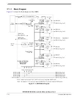
The eMIOS builds on the MIOS concept by using a unified channel module that provides a superset of the
functionality of all the individual MIOS channels, while providing a consistent user interface. This allows
more flexibility as each unified channel can be programmed for different functions.
17.1.3
Features
•
24 unified channels
•
Unified channels features
— 24-bit registers for captured/match values
— 24-bit internal counter
— Internal prescaler
— Dedicated output pin for buffer direction control
— Selectable time base
— Can generate its own time base
•
Four 24-bit wide counter buses
— Counter bus A can be driven by unified channel 23 or by the STAC bus.
— Counter bus B, C, and D are driven by unified channels 0, 8, and 16, respectively.
— Counter bus A can be shared among all unified channels. UCs 0 to 7, 8 to 15, and 16 to 23 can
share counter buses B, C, and D, respectively.
•
One global prescaler
•
Shared time bases through the counter buses
•
Synchronization among internal and external time bases
•
Shadow FLAG register
•
State of module can be frozen for debug purposes
•
DMA request capability for some channels
•
Motor control capability
17.1.4
Modes of Operation
17.1.4.1
eMIOS Modes
The eMIOS operates in one of the modes described below:
•
User mode
This is the normal operating mode. When EMIOS_MCR[FRZ] = 0, and EMIOS_CCR[FREN] =
0, the eMIOS is in user mode.
•
Debug mode
Debug mode is individually programmed for each channel. When entering this mode, the UC
registers’ contents are frozen, but remain available for read and write access through the slave
interface. After leaving debug mode, all counters that were frozen upon debug mode entry will
resume at the point where they were frozen.
In debug mode, all clocks are running and all registers are accessible; thus, this mode is not
intended for power saving, but for use during software debugging.
Содержание MPC5553
Страница 5: ...MPC5553 MPC5554 Microcontroller Reference Manual Rev 5 2 Freescale Semiconductor...
Страница 21: ...MPC5553 MPC5554 Microcontroller Reference Manual Rev 5 xvi Freescale Semiconductor...
Страница 47: ...MPC5553 MPC5554 Microcontroller Reference Manual Rev 5 1 26 Freescale Semiconductor...
Страница 163: ...MPC5553 MPC5554 Microcontroller Reference Manual Rev 5 4 20 Freescale Semiconductor...
Страница 179: ...MPC5553 MPC5554 Microcontroller Reference Manual Rev 5 5 16 Freescale Semiconductor...
Страница 561: ...MPC5553 MPC5554 Microcontroller Reference Manual Rev 5 13 38 Freescale Semiconductor...
Страница 615: ...MPC5553 MPC5554 Microcontroller Reference Manual Rev 5 14 54 Freescale Semiconductor...
Страница 707: ...MPC5553 MPC5554 Microcontroller Reference Manual Rev 5 17 68 Freescale Semiconductor...
Страница 755: ...MPC5553 MPC5554 Microcontroller Reference Manual Rev 5 18 48 Freescale Semiconductor...
Страница 873: ...MPC5553 MPC5554 Microcontroller Reference Manual Rev 5 19 118 Freescale Semiconductor...
Страница 984: ...MPC5553 MPC5554 Microcontroller Reference Manual Rev 5 Freescale Semiconductor 21 41...
Страница 985: ...MPC5553 MPC5554 Microcontroller Reference Manual Rev 5 21 42 Freescale Semiconductor...
Страница 1019: ...MPC5553 MPC5554 Microcontroller Reference Manual Rev 5 22 34 Freescale Semiconductor...
Страница 1129: ...MPC5553 MPC5554 Microcontroller Reference Manual Rev 5 25 90 Freescale Semiconductor...
Страница 1207: ...Revision History 4 Freescale Semiconductor...


