


MPC5553/MPC5554 Microcontroller Reference Manual, Rev. 5
4-8
Freescale Semiconductor
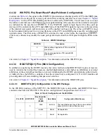
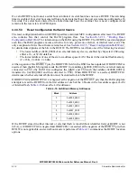
The PLLCFG[0:1] and RSTCFG pins determine the configuration of the FMPLL. If the RSTCFG pin is
asserted at the negation of RSTOUT, the PLLCFG[0:1] pins set the operating mode of the FMPLL. If
RSTCFG is asserted anytime during the assertion of RSTOUT, the FMPLL will switch to the mode
specified by the PLLCFG[0:1] pins. The values on the RSTCFG and the PLLCFG[0:1] pins must be kept
constant after RSTCFG is asserted to avoid transient mode changes in the FMPLL. If RSTCFG is in the
negated state at the negation of RSTOUT, the FMPLL defaults to enabled with a crystal reference. See
Chapter 11, “Frequency Modulated Phase Locked Loop (FMPLL) and System Clocks
,”
for more details
on the operation of the FMPLL and the PLLCFG[0:1] pins.
The signal on the WKPCFG pin determines whether weak pull up or pull down devices are enabled after
reset on the eTPU and eMIOS pins. The WKPCFG pin is applied starting at the assertion of the internal
reset signal, as indicated by the assertion of RSTOUT. Refer to
for information on WKPCFG and RSTOUT.
After the RESET input pin is negated, the reset controller checks if the FMPLL is locked. The internal
reset signal and RSTOUT are kept asserted until the FMPLL is locked. After the FMPLL is locked, the
reset controller waits an additional predetermined number of clock cycles (See
”) before negating the RSTOUT pin. The WKPCFG and BOOTCFG[0:1] pins are
sampled 4 clock cycles before the negation of RSTOUT, and the associated bits/fields are updated in the
SIU_RSR (note that the BOOTCFG[0:1] pins are only sampled if RSTCFG is asserted). In addition, the
PORS and ERS bits are set, and all other reset status bits are cleared in the reset status register.
4.4.2.3.2
External Reset
When the reset controller detects assertion of the RESET pin, the internal reset signal and RSTOUT are
asserted. Starting at the assertion of the internal reset signal (as indicated by assertion of RSTOUT), the
value on the WKPCFG pin is applied; at the same time the PLLCFG[0:1] values are applied if RSTCFG
is asserted. After the RESET pin is negated and the FMPLL loss of lock request signal is negated, the reset
controller waits the predetermined number of clock cycles (see
Section 4.2.2, “Reset Output (RSTOUT)
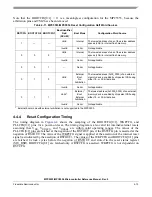
After the clock count finishes, the WKPCFG and BOOTCFG[0:1] pins are sampled (note that the
BOOTCFG[0:1] pins are only sampled if RSTCFG is asserted). The reset controller then waits 4 clock
cycles before the negating RSTOUT, and the associated bits/fields are updated in the SIU_RSR. In
addition, the ERS bit is set, and all other reset status bits in the SIU_RSR are cleared.
4.4.2.3.3
Loss-of-Lock Reset
A loss-of-lock reset occurs when the FMPLL loses lock and the loss-of-lock reset enable (LOLRE) bit in
the FMPLL synthesizer control register (FMPLL_SYNCR) is set. The internal reset signal is asserted (as
indicated by assertion of RSTOUT). Starting at the assertion of the internal reset signal (as indicated by
assertion of RSTOUT), the value on the WKPCFG pin is applied; at the same time the PLLCFG[0:1]
values are applied if RSTCFG is asserted. After the FMPLL locks, the reset controller waits until the
predetermined clock count finishes (See
Section 4.2.2, “Reset Output (RSTOUT)
”) and then the
WKPCFG and BOOTCFG[0:1] pins are sampled (note that the BOOTCFG[0:1] pins are only sampled if
RSTCFG is asserted). The reset controller then waits 4 clock cycles before negating RSTOUT, and the
associated bits/fields are updated in the SIU_RSR. In addition, the LLRS bit is set, and all other reset status
bits in the SIU_RSR are cleared. Refer to
Chapter 11, “Frequency Modulated Phase Locked Loop
,”
for more information on loss-of-lock.
4.4.2.3.4
Loss-of-Clock Reset
A loss-of-clock reset occurs when the FMPLL detects a failure in either the reference signal or FMPLL
output, and the loss-of-clock reset enable (LOCRE) bit in the FMPLL_SYNCR is set. The internal reset
signal is asserted (as indicated by assertion of RSTOUT). Starting at the assertion of the internal reset
Содержание MPC5553
Страница 5: ...MPC5553 MPC5554 Microcontroller Reference Manual Rev 5 2 Freescale Semiconductor...
Страница 21: ...MPC5553 MPC5554 Microcontroller Reference Manual Rev 5 xvi Freescale Semiconductor...
Страница 47: ...MPC5553 MPC5554 Microcontroller Reference Manual Rev 5 1 26 Freescale Semiconductor...
Страница 163: ...MPC5553 MPC5554 Microcontroller Reference Manual Rev 5 4 20 Freescale Semiconductor...
Страница 179: ...MPC5553 MPC5554 Microcontroller Reference Manual Rev 5 5 16 Freescale Semiconductor...
Страница 561: ...MPC5553 MPC5554 Microcontroller Reference Manual Rev 5 13 38 Freescale Semiconductor...
Страница 615: ...MPC5553 MPC5554 Microcontroller Reference Manual Rev 5 14 54 Freescale Semiconductor...
Страница 707: ...MPC5553 MPC5554 Microcontroller Reference Manual Rev 5 17 68 Freescale Semiconductor...
Страница 755: ...MPC5553 MPC5554 Microcontroller Reference Manual Rev 5 18 48 Freescale Semiconductor...
Страница 873: ...MPC5553 MPC5554 Microcontroller Reference Manual Rev 5 19 118 Freescale Semiconductor...
Страница 984: ...MPC5553 MPC5554 Microcontroller Reference Manual Rev 5 Freescale Semiconductor 21 41...
Страница 985: ...MPC5553 MPC5554 Microcontroller Reference Manual Rev 5 21 42 Freescale Semiconductor...
Страница 1019: ...MPC5553 MPC5554 Microcontroller Reference Manual Rev 5 22 34 Freescale Semiconductor...
Страница 1129: ...MPC5553 MPC5554 Microcontroller Reference Manual Rev 5 25 90 Freescale Semiconductor...
Страница 1207: ...Revision History 4 Freescale Semiconductor...


