


MPC5553/MPC5554 Microcontroller Reference Manual, Rev. 5
2-36
Freescale Semiconductor
2.3
Detailed Signal Description
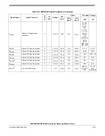
This section describes the signals for the MPC5553/MPC5554.
2.3.1
Reset / Configuration Signals
2.3.1.1
External Reset Input
RESET
The RESET input is asserted by an external device to reset the all modules of the MPC5553/MPC5554
MCU. The RESET pin must be asserted during a power-on reset. Refer to
2.3.1.2
External Reset Output
RSTOUT
The RSTOUT output is a push/pull output asserted during an internal MPC5553/MPC5554 reset. The
RSTOUT can also be asserted by software without causing an internal reset of the MPC5553/MPC5554
MCU. Refer to
Section 4.2.2, “Reset Output (RSTOUT)
NOTE
During an internal power-on reset (POR), RSTOUT is tri-stated.
2.3.1.3
PLL Configuration 0 / External Interrupt Request / GPIO
PLLCFG[0]_IRQ[4]_GPIO[208]
PLLCFG[0]_IRQ[4]_GPIO[208] are sampled on the negation of the RESET input pin, if the RSTCFG pin
is asserted at that time. The values are used to configure the FMPLL mode of operation. The alternate
function is external interrupt request input.
2.3.1.4
PLL Configuration 1 / External Interrupt Request / DSPI D Data Out / GPIO
PLLCFG[1]_IRQ[5]_SOUTD_GPIO[209]
PLLCFG[1]_IRQ[5]_SOUTD_GPIO[209] are sampled on the negation of the RESET input pin, if the
RSTCFG pin is asserted at that time. The values are used to configure the FMPLL mode of operation. The
alternate functions are external interrupt request input, and data output for the DSPI module D.
2.3.1.5
Reset Configuration Input / GPIO
RSTCFG_GPIO[210]
The RSTCFG input is used to enable the BOOTCFG[0:1] and PLLCFG[0:1] pins during reset. If RSTCFG
is negated during reset, the BOOTCFG and PLLCFG pins are not sampled at the negation of RSTOUT. In
that case, the default values for BOOTCFG and PLLCFG are used. If RSTCFG is asserted during reset,
the values on the BOOTCFG and PLLCFG pins are sampled and configure the boot and FMPLL modes.
Содержание MPC5553
Страница 5: ...MPC5553 MPC5554 Microcontroller Reference Manual Rev 5 2 Freescale Semiconductor...
Страница 21: ...MPC5553 MPC5554 Microcontroller Reference Manual Rev 5 xvi Freescale Semiconductor...
Страница 47: ...MPC5553 MPC5554 Microcontroller Reference Manual Rev 5 1 26 Freescale Semiconductor...
Страница 163: ...MPC5553 MPC5554 Microcontroller Reference Manual Rev 5 4 20 Freescale Semiconductor...
Страница 179: ...MPC5553 MPC5554 Microcontroller Reference Manual Rev 5 5 16 Freescale Semiconductor...
Страница 561: ...MPC5553 MPC5554 Microcontroller Reference Manual Rev 5 13 38 Freescale Semiconductor...
Страница 615: ...MPC5553 MPC5554 Microcontroller Reference Manual Rev 5 14 54 Freescale Semiconductor...
Страница 707: ...MPC5553 MPC5554 Microcontroller Reference Manual Rev 5 17 68 Freescale Semiconductor...
Страница 755: ...MPC5553 MPC5554 Microcontroller Reference Manual Rev 5 18 48 Freescale Semiconductor...
Страница 873: ...MPC5553 MPC5554 Microcontroller Reference Manual Rev 5 19 118 Freescale Semiconductor...
Страница 984: ...MPC5553 MPC5554 Microcontroller Reference Manual Rev 5 Freescale Semiconductor 21 41...
Страница 985: ...MPC5553 MPC5554 Microcontroller Reference Manual Rev 5 21 42 Freescale Semiconductor...
Страница 1019: ...MPC5553 MPC5554 Microcontroller Reference Manual Rev 5 22 34 Freescale Semiconductor...
Страница 1129: ...MPC5553 MPC5554 Microcontroller Reference Manual Rev 5 25 90 Freescale Semiconductor...
Страница 1207: ...Revision History 4 Freescale Semiconductor...


