


MPC5553/MPC5554 Microcontroller Reference Manual, Rev. 5
14-48
Freescale Semiconductor
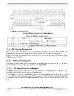
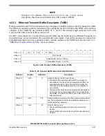
14.5.1.1
Driver/DMA Operation with Transmit BDs
Typically a transmit frame will be divided between multiple buffers. An example is to have an application
payload in one buffer, TCP header in a second buffer, IP header in a third buffer, Ethernet/IEEE
802.3
header in a fourth buffer. The Ethernet MAC does not prepend the Ethernet header (destination address,
source address, length/type fields), so this must be provided by the driver in one of the transmit buffers.
The Ethernet MAC can append the Ethernet CRC to the frame. Whether the CRC is appended by the MAC
or by the driver is determined by the TC bit in the transmit BD which must be set by the driver.
The driver (TxBD software producer) should set up Tx BDs in such a way that a complete transmit frame
is given to the hardware immediately. If a transmit frame consists of three buffers, the BDs should be
initialized with pointer, length and control (W, L, TC, ABC) and then the TxBD[R] bits should be set = 1
in reverse order (3rd, 2nd, 1st BD) to insure that the complete frame is ready in memory before the DMA
begins. If the TxBDs are set up in order, the DMA Controller could DMA the first BD before the 2nd was
made available, potentially causing a transmit FIFO underrun.
In the FEC, the DMA is notified by the driver that new transmit frames are available by writing to the
TDAR register. When this register is written to (data value is not significant) the FEC RISC will tell the
DMA to read the next transmit BD in the ring. After it is started, the RISC + DMA will continue to read
and interpret transmit BDs in order and DMA the associated buffers, until a transmit BD is encountered
with the R bit = 0. At this point the FEC will poll this BD one more time. If the R bit = 0 the second time,
then the RISC will stop the transmit descriptor read process until software sets up another transmit frame
and writes to TDAR.
When the DMA of each transmit buffer is complete, the DMA writes back to the BD to clear the R bit,
indicating that the hardware consumer is finished with the buffer.
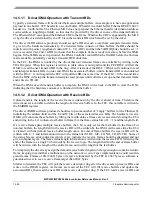
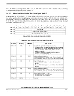
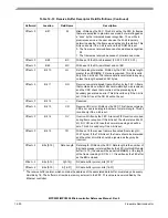
14.5.1.2
Driver/DMA Operation with Receive BDs
Unlike transmit, the length of the receive frame is unknown by the driver ahead of time. Therefore the
driver must set a variable to define the length of all receive buffers. In the FEC, this variable is written to
the EMRBR register.
The driver (RxBD software producer) should set up some number of “empty” buffers for the Ethernet by
initializing the address field and the E and W bits of the associated receive BDs. The hardware (receive
DMA) will consume these buffers by filling them with data as frames are received and clearing the E bit
and writing to the L (1 indicates last buffer in frame) bit, the frame status bits (if L = 1) and the length field.
If a receive frame spans multiple receive buffers, the L bit is only set for the last buffer in the frame. For
non-last buffers, the length field in the receive BD will be written by the DMA (at the same time the E bit
is cleared) with the default receive buffer length value. For end of frame buffers the receive BD will be
written with L = 1 and information written to the status bits (M, BC, MC, LG, NO, CR, OV, TR). Some of
the status bits are error indicators which, if set, indicate the receive frame should be discarded and not
given to higher layers. The frame status/length information is written into the receive FIFO following the
end of the frame (as a single 32-bit word) by the receive logic. The length field for the end of frame buffer
will be written with the length of the entire frame, not just the length of the last buffer.
For simplicity the driver may assign the default receive buffer length to be large enough to contain an entire
frame, keeping in mind that a malfunction on the network or out of spec implementation could result in
giant frames. Frames of 2K (2048) bytes or larger are truncated by the FEC at 2047 bytes so software is
guaranteed never to see a receive frame larger than 2047 bytes.
Similar to transmit, the FEC will poll the receive descriptor ring after the driver sets up receive BDs and
writes to the RDAR register. As frames are received the FEC will fill receive buffers and update the
associated BDs, then read the next BD in the receive descriptor ring. If the FEC reads a receive BD and
Содержание MPC5553
Страница 5: ...MPC5553 MPC5554 Microcontroller Reference Manual Rev 5 2 Freescale Semiconductor...
Страница 21: ...MPC5553 MPC5554 Microcontroller Reference Manual Rev 5 xvi Freescale Semiconductor...
Страница 47: ...MPC5553 MPC5554 Microcontroller Reference Manual Rev 5 1 26 Freescale Semiconductor...
Страница 163: ...MPC5553 MPC5554 Microcontroller Reference Manual Rev 5 4 20 Freescale Semiconductor...
Страница 179: ...MPC5553 MPC5554 Microcontroller Reference Manual Rev 5 5 16 Freescale Semiconductor...
Страница 561: ...MPC5553 MPC5554 Microcontroller Reference Manual Rev 5 13 38 Freescale Semiconductor...
Страница 615: ...MPC5553 MPC5554 Microcontroller Reference Manual Rev 5 14 54 Freescale Semiconductor...
Страница 707: ...MPC5553 MPC5554 Microcontroller Reference Manual Rev 5 17 68 Freescale Semiconductor...
Страница 755: ...MPC5553 MPC5554 Microcontroller Reference Manual Rev 5 18 48 Freescale Semiconductor...
Страница 873: ...MPC5553 MPC5554 Microcontroller Reference Manual Rev 5 19 118 Freescale Semiconductor...
Страница 984: ...MPC5553 MPC5554 Microcontroller Reference Manual Rev 5 Freescale Semiconductor 21 41...
Страница 985: ...MPC5553 MPC5554 Microcontroller Reference Manual Rev 5 21 42 Freescale Semiconductor...
Страница 1019: ...MPC5553 MPC5554 Microcontroller Reference Manual Rev 5 22 34 Freescale Semiconductor...
Страница 1129: ...MPC5553 MPC5554 Microcontroller Reference Manual Rev 5 25 90 Freescale Semiconductor...
Страница 1207: ...Revision History 4 Freescale Semiconductor...


