EDA 2530 Commissioning Procedure for Cable and Wireless Access
1/153 22-FGC 101 0239/2 Uen Rev J 2010-04-01
©
Ericsson AB 2010
Commercial in confidence
69 (200)
7.1
Configure The Optical SFP Modules Gigabit Ethernet
Note1
: If the EDA 2530 is to be the “Parent” node & subtend an existing
EDA 2510 node, then the backhaul SFP required for Port 1 (
SU57AE
1310nm)
will be recovered from the EDA 2510 SFP Port 3 when the two
nodes are migrated during a PEW, at a later date.
Note2
: CP Port SFP1 will be utilised as the Network interface to backhaul to
the IP Network.
Note3
: CP Port SFP2 (when fitted) will be used by the “Parent” to subtend
the “Child#1”, an EDA 2510 node.
Note4
: CP Port SFP3 (when fitted) will be used by the “Parent” to subtend
the “Child#2”, an EDA 2530 node.
Note5
: CP Port SFP4 (when fitted) will be used by the “Parent” to subtend
the “Child#3”, an EDA 2530 node.
Note6:
SFP Modules approved by Marconi are ‘Moni Tagged’ and will be
configured automatically when inserted.
a.
On the Common Part card:- (Check details with the site’s SID document)
Insert SFP1 module (if available) into Port 1 (SU57AE - 1310nm).
Insert SFP2 module (if supplied) into Port 2 (SU57AD - 850nm).
Insert SFP3 module (if supplied) into Port 3 (SU57AD - 850nm).
Insert SFP4 module (if supplied) into Port 4 (SU57AD - 850nm).
b.
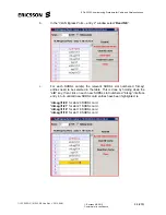
Right click on the CP Card and select
SFP Provisioning
from the sub
menu. The “CP-IP SFP/Port Provisioning” screen will appear.

