EDA 2530 Commissioning Procedure for Cable and Wireless Access
1/153 22-FGC 101 0239/2 Uen Rev J 2010-04-01
©
Ericsson AB 2010
Commercial in confidence
143 (200)
e.
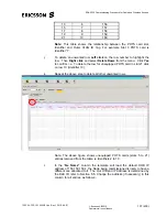
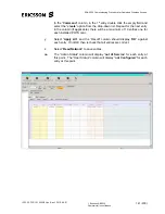
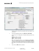
In the “
Ne Name”
column the template will load the default OOB IP
address of 150.150.150.4, the Node being commissioned is likely to have a
different one allocated to it. The Out Of Band IP Address is determined by
the DLE ID, refer to Section 5.5. Change the address (if necessary) in this
column for all entries, as follows:-
Change the 1
st
entry in this column to the correct IP address, select the 1
st
entry, then left-click the 1
st
entry & drag down to the bottom of the column
to highlight all entries. Right click & select “
Replicate cell
”, all entries in the
“
Ne Name”
column will now be set to the required OOB IP Address.
f.
For Information only:
For each POTS line card the “
Virtual GW Index”
column should have the correct Index number for the occupied slot. (e.g.
Slot 3 = Index 1, Slot 5 = Index 2,………. Slot 19 = Index 9, Slot 21 = Index
10)
g.
In the “
Media Local IP Address (4.21 only)”
column, the POTS card slot
IP Address must be entered. This address is unique for each POTS line
card for the slot position and is also site specific. This is specified in the
“CWA Voice Card Deployment” spreadsheet.
Change the 1
st
entry in this column to the unique IP address for the
required POTS card, select the 1
st
entry, then left-click the 1
st
entry & drag
down to the bottom of the column to highlight all 64 entries. Right click &
select “
Replicate cell
”, all entries in the “Media Local IP Address
”
column
will now be set to the required POTS card IP Address.
h.
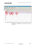
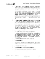
Select the “
Application Control
” tab.
i.
Under the “
Command
” column, set all 64 entries to “
create
”.
In the “
Command
” column, in the 1
st
entry double click the empty field and
select the “
create
” option from the drop-down list. Select the 1
st
entry, then
click & drag down to the bottom to highlight all 64 entries. Right click &
select “
Replicate cell
”, all 64 entries in the “
Command”
column will now
be set to “
create
”.
j. Select
“
Apply All
” and wait for all 64 entries to turn green
k. Select
“
Read Network
”.
l.
If more that one POTS line card is installed then repeat steps b to k, to
configure the H248 Terminations for the each additional installed POTS line
card.
m.
Select the “
Termination
” tab again.
n. Select
“
Read Network
” to prove all entries have been built.
o.
Under the “
Admin Status
” column, set all entries to “
Unblock
”.


