Functions 14. Option Slots
138
RC700-D Rev.2
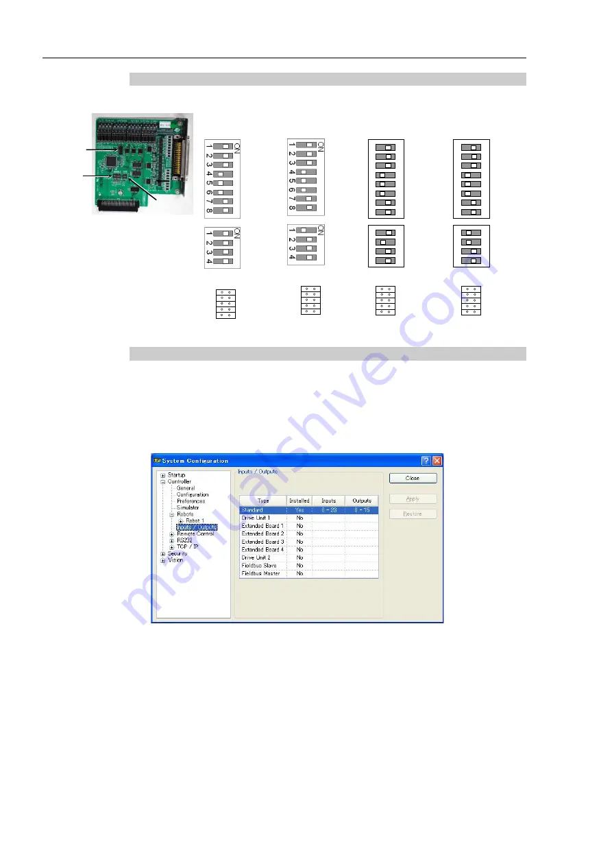
14.2.2 Board Configuration (Expansion I/O Board)
Board Appearance
Switch and Jumper Configuration
DSW2
DSW1
CN3
Setup the DSW1 and DSW2. CN3 is all open.
1
st
board
2
nd
board
3
rd
board
4
th
board
SW1
SW2
SW3
SW4
DS
W
1
SW1
SW2
SW3
SW4
SW5
SW6
SW7
SW8
DS
W
2
CN3
1 2
9 10
SW1
SW2
SW3
SW4
DS
W
2
SW1
SW2
SW3
SW4
SW5
SW6
SW7
SW8
DS
W
1
CN3
1 2
9 10
SW4
SW3
SW2
SW1
DS
W
2
ON
123
4
SW8
SW7
SW6
SW5
SW4
SW3
SW2
SW1
123
45
67
8
ON
DS
W
1
CN
3
1 2
9 10
SW4
SW3
SW2
SW1
DS
W
2
ON
123
4
SW8
SW7
SW6
SW5
SW4
SW3
SW2
SW1
123
45
67
8
ON
DS
W
1
CN
3
1 2
9 10
14.2.3 Confirmation with EPSON RC+ 7.0 (Expansion I/O Board)
When an expansion I/O board is mounted to the option unit, the Controller software automatically identifies the
expansion I/O board. Therefore, no software configuration is needed.
Correct identification can be confirmed from EPSON RC+ 7.0.
(1)
Select the EPSON RC+ 7.0 menu-[Setup]-[System Configuration] to display the
[System Configuration] dialog.
(2)
Select [Controller]-[Inputs / Outputs].
(3)
Make sure that “Yes” is displayed in the Installed column.
The expansion I/O board is identified by the Controller software. Corresponding Input
and Output is available.
Содержание RC700-D
Страница 1: ...Control Unit RC700 D Original instructions Rev 2 EM221C5146F ROBOT CONTROLLER RC700 D Manual ...
Страница 2: ...ROBOT CONTROLLER RC700 D Manual Rev 2 ...
Страница 8: ...vi RC700 D Rev 2 ...
Страница 16: ...Table of Contents xiv RC700 D Rev 2 ...
Страница 18: ......
Страница 80: ...Installation 5 Second Step 64 RC700 D Rev 2 ...
Страница 82: ......
Страница 87: ...Functions 1 Specifications RC700 D Rev 2 71 1 3 Outer Dimensions Unit mm ...
Страница 182: ...Functions 14 Option Slots 166 RC700 D Rev 2 14 8 6 Circuit Overview EUROMAP67 Board EUROMAP67 Board System diagram ...
Страница 190: ......
Страница 202: ...Regular Inspection 3 Alarm 186 RC700 D Rev 2 ...
Страница 203: ...187 Appendix ...
Страница 204: ......


