Functions 2. Part Names and Functions
72
RC700-D Rev.2
2. Part Names and Functions
RC700-D
(2)
(3)
(1)
(Left side)
(4)
(5)
(6)
(7)
(8)
(9)
(10)
(11)
(12) (13)
(14)
(15)
(16) (17) (18)(19) (20)
(21)
(22)
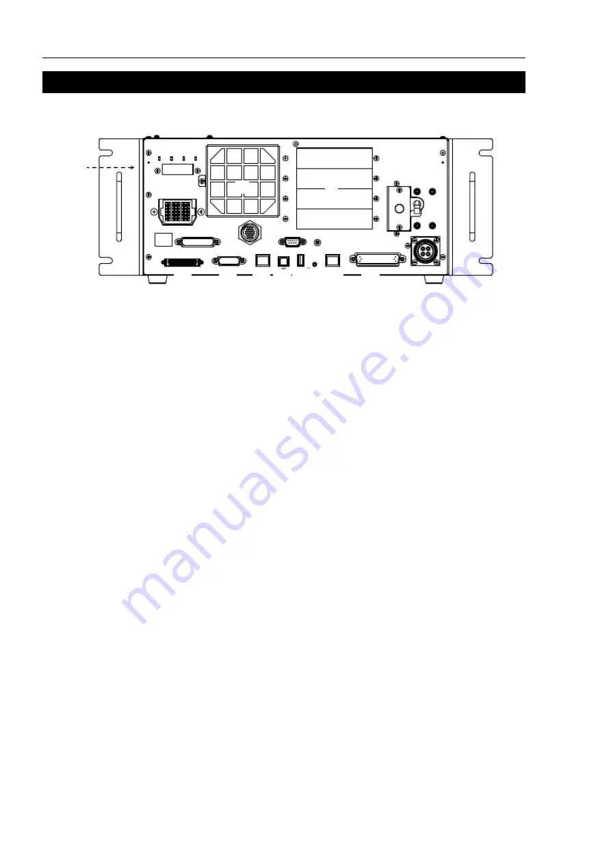
(1) Signature label (top panel)
The serial number of the Controller and other information are shown.
(2) LED
The LED indicates current operation mode.
(TEST, TEACH, AUTO, PROGRAM)
For details, refer to
2.1 LED & Seven Segment LED
(3) Seven-segment Display
Four-digit seven-segment LED displays the line number and the status of the
Controller (error number, warning number, status of Emergency Stop and Safety
Door).
For details, refer to
2.1 LED & Seven Segment LED.
(4) M/C POWER connector
A connector for the Manipulator power source.
Connect the dedicated power cable attached to the Manipulator.
(5) Fan Filter
A protective filter is installed in front of the fan to filter out dust.
Check the condition of the filter regularly and clean it when necessary. A dirty filter
may result in malfunction of the robot system due to temperature rise of the Drive Unit.
For inspection, cleaning, and replacement, refer to the
Maintenance 4.1 Fan Filter
,
4.2
Fan.
(6) Option slot
Option boards such as expansion I/O board, Fieldbus I/O board, RS-232C board, PG
board, Analog I/O board, and Force Sensor I/F board can be installed. Four slots are
available.
For details, refer to
14. Option Slots.
(7) Battery
A lithium battery for data backup.
(8) POWER switch
Turns ON or OFF the Controller.
Содержание RC700-D
Страница 1: ...Control Unit RC700 D Original instructions Rev 2 EM221C5146F ROBOT CONTROLLER RC700 D Manual ...
Страница 2: ...ROBOT CONTROLLER RC700 D Manual Rev 2 ...
Страница 8: ...vi RC700 D Rev 2 ...
Страница 16: ...Table of Contents xiv RC700 D Rev 2 ...
Страница 18: ......
Страница 80: ...Installation 5 Second Step 64 RC700 D Rev 2 ...
Страница 82: ......
Страница 87: ...Functions 1 Specifications RC700 D Rev 2 71 1 3 Outer Dimensions Unit mm ...
Страница 182: ...Functions 14 Option Slots 166 RC700 D Rev 2 14 8 6 Circuit Overview EUROMAP67 Board EUROMAP67 Board System diagram ...
Страница 190: ......
Страница 202: ...Regular Inspection 3 Alarm 186 RC700 D Rev 2 ...
Страница 203: ...187 Appendix ...
Страница 204: ......


