ii
Rev. I
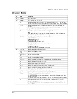
9-24,27,28,37
Added the explanation for disassembly and assemblyof the parts below.
-PCI card
-Switch cable assembly
9-29
The method of disassembly and assembly the CD/FDD bracket is changed.
The changed point.
One screw and stopper is added to fix the CD/FDD bracket correctly.
Reason for change;
The part is changed to prevent the CD/FDD bracket from connection failure.
B-11—15
Added parts list and block diagram for the model DM-M820-015.
Reason for change;
The display with the touch panel assembly and without the MSR unit is newly supplied.
Rev.D
9-19
Added the explanation of attaching the touch panel.
Reason for change;
To be supplied the touch panel unit (115) newly.
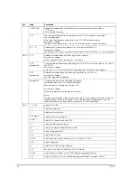
9-30
Appendix B
Changed the explanation of attaching the CD-ROM unit with the screws “C.B.screw.
2x2.5.F/ZN”.
Reason for change;
T wo screws “C.B.screw. 2x2.5.F/ZN“ attaching the CD-ROM unit are added.
9-32
Appendix B
Deleted the explanation of attaching the gasket to the FDD unit.
Reason for change;
We stop supplying the gasket.
Appendix B
Changed the partslist and Exploded Diagrams.
The added parts in the list is indicated below.
Touch panel unit (Reference number: 115)
Reason for change;
To be changed the composition of the parts.
Note;
The parts (Touch panel, Upper plate, Lower plate, Touch panel asssembly) will be not
supplied. Because the touch panel unit will be supplied instead of them. And the
touch panel assembly and the touch panel unit is interchangeality.
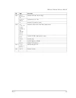
Rev.E
1-1,7,9-37
Add the 2.5”HDD.
1-3
Add the Inside view.
1-7
Add the Lithium Battery.
1-8,9,AppB
Add the Gray color Models.
5-12,27
Add the On board Lan Boot ROM.
6-2
Add the Adjusting the volume.
8-8
Add the Unable to Read Data from HDD.
8-11
Add the Speaker Faults.
9-29
Add the RAID Card.
9-31,34
Add the Power cable is differentn for 3.5”HDD or 2.5”HDD.
9-45
Add the Speaker.
A-1
Add the 2.5”HDD Jumper Settings.
B-16
Revision of the Parts list IM-800 for 3.5”HDD Model.
B-19,20
Add the Parts list IM-800 for 2.5”HDD Model and Speaker Model.
B-21
Add the IM-800 for 2.5”HDD Model and Speaker Model Component Block.
Rev.
Page
Description
Содержание DM-M820
Страница 1: ...Technical Reference Manual MR Series English 403308709 Rev I EPSON ...
Страница 2: ......
Страница 20: ...xviii Rev I ...
Страница 42: ...2 8 Setup for the IM 800 and the DM M820 Rev I ...
Страница 50: ...3 8 Hardware Specifications Rev I ...
Страница 178: ...5 38 BIOS Functions Rev I ...
Страница 216: ...8 26 Troubleshooting Rev I ...
Страница 270: ...9 54 Disassembly and Assembly Rev I 6 Remove the HDD cable 216 from the Main circuit board HDD cable ...
Страница 323: ......
Страница 324: ...SEIKO EPSON CORPORATION EPSON ...

