Rev. I
Disassembly and Assembly
9-15
MR Series Technical Reference Manual
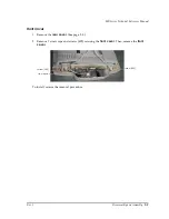
LCD Circuit Board
Follow the steps below for disassembly for the model DM-M820-014/024 and DM-M820-015/
025.
1. Remove the
rear case
. (See page 9-11.)
2. Remove 4 hex screws (S07) (two each for the two connectors). (See page 9-13.)
3. Remove 10 screws (S05) securing the rear panel to the LCD assembly. After that remove the
rear panel. (See page 9-13.)
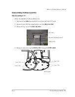
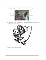
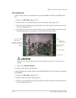
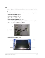
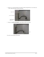
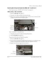
4. Disconnect the 4 cables shown below. Remove 2 screws (1050) holding 2 ground wires and
lift up the ground wires, then remove 2 screws (1050) securing the plate.
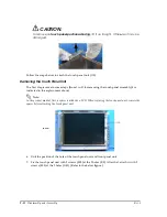
CAUTION:
Remove the cable on the right side very carefully because its connection is not
strong.
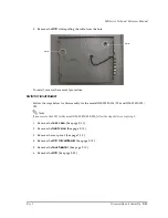
5. Remove the
LCD circuit board
.
To install, reverse the removal procedure.
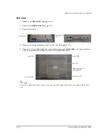
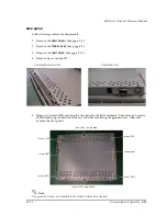
Follow the steps below for disassembly for the model DM-M820-013/023 (without a touch panel
and an MSR).
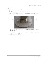
1. Remove the
rear case
. (See page 9-11.)
2. Remove 2 hex screws (S07). (See page 9-13.)
3. Remove 10 screws (S05) securing the rear panel to the LCD assembly. After that remove the
rear panel. (See page 9-13.)
screw (1050) and
ground wire
cable: See
Caution below
screw (1050) and
ground wire
LCD circuit board
cables
screws (1050)
cable
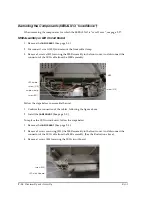
cables connected to
the switch circuit board
Содержание DM-M820
Страница 1: ...Technical Reference Manual MR Series English 403308709 Rev I EPSON ...
Страница 2: ......
Страница 20: ...xviii Rev I ...
Страница 42: ...2 8 Setup for the IM 800 and the DM M820 Rev I ...
Страница 50: ...3 8 Hardware Specifications Rev I ...
Страница 178: ...5 38 BIOS Functions Rev I ...
Страница 216: ...8 26 Troubleshooting Rev I ...
Страница 270: ...9 54 Disassembly and Assembly Rev I 6 Remove the HDD cable 216 from the Main circuit board HDD cable ...
Страница 323: ......
Страница 324: ...SEIKO EPSON CORPORATION EPSON ...

