Rev. I
BIOS Functions
5-11
MR series Technical Reference Manual
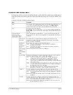
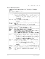
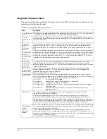
Integrated Peripherals Menu
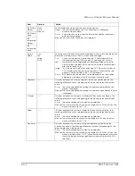
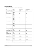
This menu sets the items related to I/O ports such as the IDE controller, the transfer mode, the
serial ports, and the parallel port.
Table A-7 Integrated Peripherals menu
Items
Description
On-Chip Primary
PCI IDE
This setting is to enable/disable the IDE controller housed in the chip set (ICH2). All of the default
settings are set as "Enabled". Always use the default "Enabled" setting.
If the "Disabled" settings are used, the IRQ resources are released and become available for
other devices. If the IRQ resources that are released, IRQ-14 is released for the primary and IRQ-
15 for the secondary.
On-Chip
Secondary PCI
IDE
IDE Primary
Master PIO
This setting sets the transfer mode for the IDE device connected to each interface. All of the
default settings are "Auto". The PIO is normally set as "Auto," but due to the auto detection
performed during POST, the optimum method used by the connection device is then set as
BIOS.
If devices in different modes are connected to the master and the slave, the transfer mode will
be fixed at a slow speed; therefore, it is necessary to pay particular attention to the connection
to each port. If a setting is made that exceeds the maximum mode supported by the device
connected, note that data errors may occur. If On-Chip Primary/Secondary PCI IDE is set to
"Disabled," the corresponding items cannot be selected.
IDE Primary
Slave PIO
IDE Secondary
Master PIO
IDE Secondary
Slave PIO
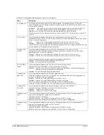
IDE Primary
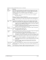
Master UDMA
This setting sets the DMA transfer mode for the IDE device connected to each interface. All
default settings are set as "Auto". The UDMA is normally set as "Auto, but due to the auto
detection performed during the POST, the DMA mode support status for the connection device
is determined as BIOS.
If any of the devices connected does not support DMA mode, the maximum mode that
device supports will be set. If On-Chip Primary/Secondary PCI IDE is set to "Disabled," the
corresponding items cannot be changed.
When using the UDMA, set as “Auto“
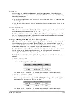
The transfer mode for the DMA mode compatible device connected to the IDE interface in
each OS can be changed to the DMA mode using the following methods. For BIOS settings, set
IDE ... UDMA to "Auto." This has been supported for the OS for EPSON.
1. MS-DOS)
Do not set the DMA mode.
2. Windows NT
Using a tool in Service Pack 6a, Refer to “Chapter 4“
3. Windows 98
Setting the OS, Refer to “Chapter 4“
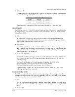
4. Windows 2000
By applying Chip Set Driver, the mode can be automatically changed to
the DMA mode.
5. Windows XP
The DMA mode is automatically set upon installing the Windows XP
operating system.
IDE Primary
Slave UDMA
IDE Secondary
Master UDMA
IDE Secondary
Slave UDMA
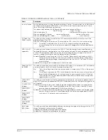
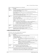
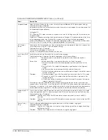
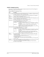
USB Controller
This setting is used to enable/disable the USB controller housed in the chip set (ICH2).
The default setting is set as "Enabled".
Perform setting according to your system configuration (whether or not a USB device is
connected). If the "Disabled" setting is used, neither USB Keyboard Support or USB Mouse
Support can be selected and these functions are not supported. The IRQ resource settings for
the USB controller is performed by using PnP/PCI Configurations: Assign IRQ For USB. Therefore, it
is not possible to release the IRQ resources by only changing this setting to "Disabled."
Also, it is not possible to set Port-0/1 (rear connector) and Port-2/3 (front connector) separately.
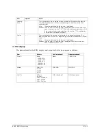
USB Keyboard
Support
This setting enables/disables each of the emulation functions for the USB keyboard and the USB
mouse. The default setting is "Disabled".
If the USB keyboard and the USB mouse are used just like the PS/2 keyboard and the PS/2
mouse because the USB is not supported such as in the case of MS-DOS or Windows NT, set
these items to "Enabled." In the case of an OS that supports the USB such as Windows 98 or later
version, use the "Disabled" settings.
If a PS/2 Mouse is used, Set the USB Mouse Support to "Disabled”.
USB Mouse
Support
Содержание DM-M820
Страница 1: ...Technical Reference Manual MR Series English 403308709 Rev I EPSON ...
Страница 2: ......
Страница 20: ...xviii Rev I ...
Страница 42: ...2 8 Setup for the IM 800 and the DM M820 Rev I ...
Страница 50: ...3 8 Hardware Specifications Rev I ...
Страница 178: ...5 38 BIOS Functions Rev I ...
Страница 216: ...8 26 Troubleshooting Rev I ...
Страница 270: ...9 54 Disassembly and Assembly Rev I 6 Remove the HDD cable 216 from the Main circuit board HDD cable ...
Страница 323: ......
Страница 324: ...SEIKO EPSON CORPORATION EPSON ...

