9-62
Disassembly and Assembly
Rev. I
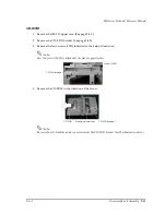
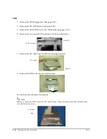
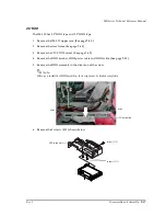
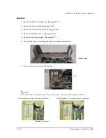
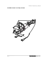
Switch cable assembly (218)
1. Remove the IM-800 upper case. (See page 9-42.)
2. Remove the CD/FDD bracket. (See page 9-49.)
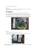
3. Disconnect switch cable assembly (218) from the connector indicated below.
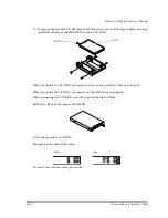
4. Disattach the hooks of the power switch from the frame back side. (The illustration below
shows the front side of the frame.)
Note:
When you attach a power switch to the frame, be careful that it is not inside out. (The direction of the
switch is indicated in the illustration above.)
power switch cable
hooks
power switch
Back side
Front side
Содержание DM-M820
Страница 1: ...Technical Reference Manual MR Series English 403308709 Rev I EPSON ...
Страница 2: ......
Страница 20: ...xviii Rev I ...
Страница 42: ...2 8 Setup for the IM 800 and the DM M820 Rev I ...
Страница 50: ...3 8 Hardware Specifications Rev I ...
Страница 178: ...5 38 BIOS Functions Rev I ...
Страница 216: ...8 26 Troubleshooting Rev I ...
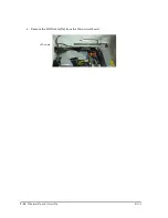
Страница 270: ...9 54 Disassembly and Assembly Rev I 6 Remove the HDD cable 216 from the Main circuit board HDD cable ...
Страница 323: ......
Страница 324: ...SEIKO EPSON CORPORATION EPSON ...

