UNDERSTANDING UPS OPERATION
Power Xpert
9395 UPS (450–550 kVA) Installation and Operation Manual
164201701 Rev 3
www.eaton.com/powerquality
6-26
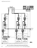
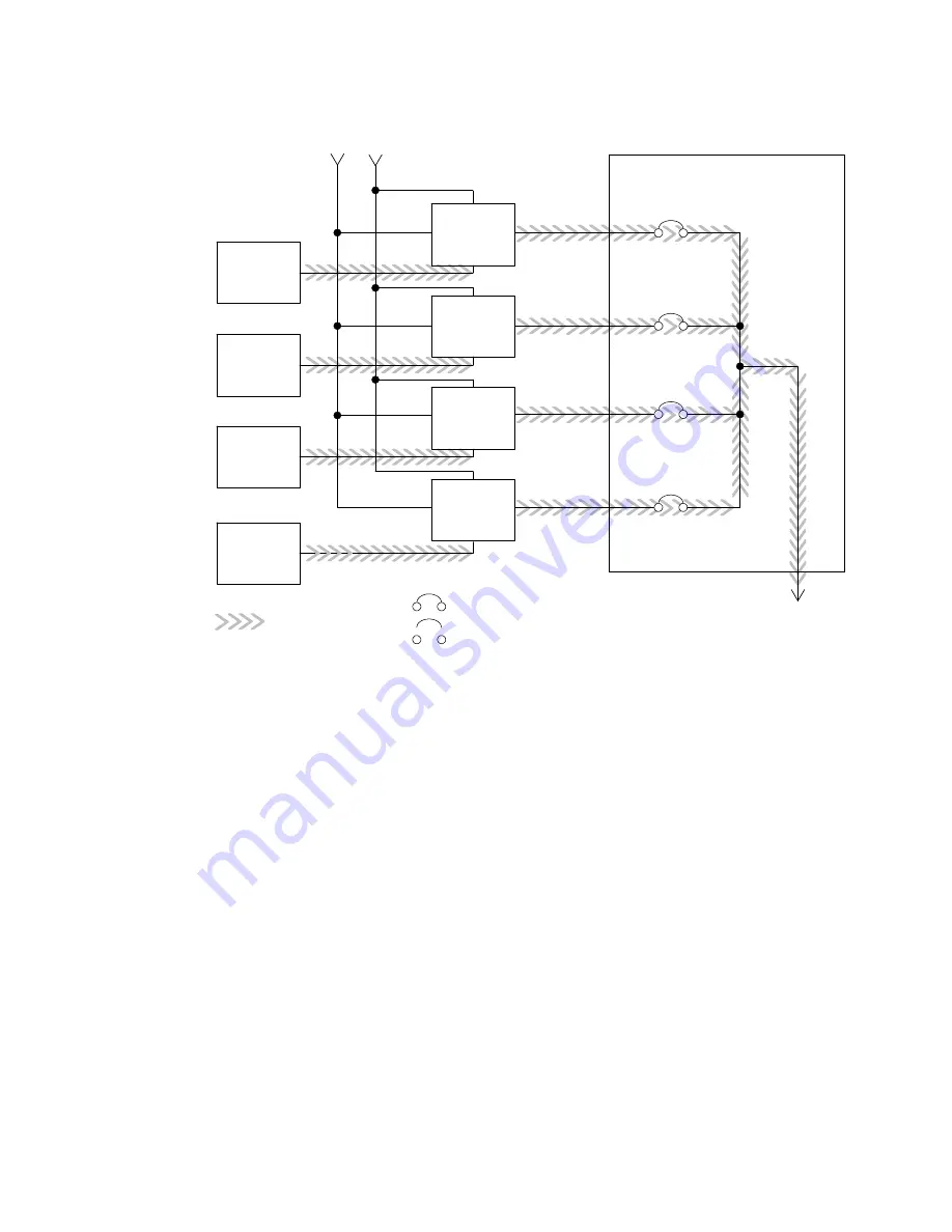
Main Power Flow
UPS 1
UPS 2
UPS 3
UPS 4
Output to
Critical Load
Battery
UPS Input
Tie Cabinet
UPS 1 Output
Bypass Input
UPS 2 Output
UPS 3 Output
UPS 4 Output
Battery
Battery
Battery
Closed
Open
Breakers
Figure 6‐21. Path of Current through the UPSs in Battery Mode – Distributed Bypass
If the input power fails to return or is not within the acceptance windows required for
normal operation, the battery continues discharging until a DC voltage level is reached
where the inverter output can no longer support the shared loads. When this event
occurs, each UPS issues another set of audible and visual alarms that indicate a
two-minute SHUTDOWN IMMINENT warning. Unless the system has a valid AC
input soon, redundant UPMs begin shutting down until there are no longer enough
UPMs online to support the connected load. When this event occurs, the system
shuts down. If the bypass source is available, the system transfers to bypass instead
of shutting down.
If at any time during the battery discharge the input power becomes available again,
the rectifier begins to supply DC current to the inverter. At this point, the UPS returns
to Normal mode. If at any time during the battery discharge the AC input power
becomes available again, each rectifier turns on, assumes the inverter load from the
batteries, and begins recharging the batteries. Depending on the total load and the
duration of the battery discharge, battery and rectifier input current limit alarms may
be seen for a short time due to the current required to recharge the batteries.
Содержание Power Xpert Plus 1
Страница 1: ...Power Xpert 9395 UPS and Plus 1 UPS 450 550 kVA Installation and Operation Manual...
Страница 193: ......
Страница 194: ...1642017013 164201701 3...


