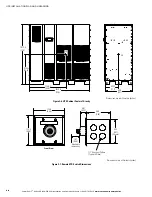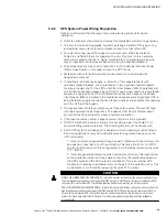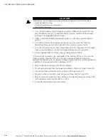
UPS INSTALLATION PLAN AND UNPACKING
Power Xpert
9395 UPS (450–550 kVA) Installation and Operation Manual
164201701 Rev 3
www.eaton.com/powerquality
3-10
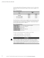
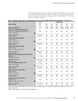
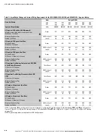
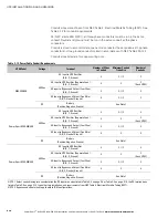
Table 3‐5. Input/Output Ratings and External Wiring Requirements for the 9395-550/450, 9395-550/500, and 9395-550/550 – Separate Battery
Basic Unit Rating
Units
Rating 50/60 Hz
kVA
kW
450
409
450
409
500
455
500
455
550
500
550
500
Input and Output Voltage
Volts
400/400
480/480
400/400
480/480
400/400
480/480
AC Input to UPS Rectifier (0.98 Minimum pF)
Full load current plus battery recharge current
(3) Phases, (1) Ground
A
Amps
741
617
823
686
905
754
Minimum Conductor Size
Number per Phase
AWG or kcmil
(each)
300
(4)
4/0
(3)
300
(4)
350
(3)
300
(4)
350
(3)
AC Input to UPS Bypass (Four Wire)
Full Load Current
(3) Phases, (1) Ground
B
Amps
650
541
722
601
794
662
Minimum Conductor Size
Number per Phase
AWG or kcmil
(each)
350
(3)
4/0
(3)
350
(3)
4/0
(3)
350
(3)
350
(3)
AC Input to UPS Bypass (Five Wire)
Full Load Current
(3) Phases, (1) Neutral, (1) Ground
B
Amps
650
541
722
601
794
662
Minimum Conductor Size
Number per Phase
AWG or kcmil
(each)
500
(3)
250
(3)
500
(3)
300
(3)
500
(3)
300
(4)
DC Input from Each Battery Cabinet to Each UPS UPM
or Each Battery Disconnect
(1) Positive, (1) Negative
C
Total Amps
902
902
1002
1002
1103
1103
Minimum Conductor Size
Number per Pole
AWG or kcmil
(each)
500
(1)
500
(1)
500
(1)
500
(1)
500
(1)
500
(1)
DC Input from Each Battery Disconnect to Each UPS
UPM
(1) Positive, (1) Negative
C
Total Amps
902
902
1002
1002
1103
1103
Minimum Conductor Size
Number per Pole
AWG or kcmil
(each)
250
(3)
4/0
(3)
250
(3)
250
(3)
250
(3)
250
(3)
AC Output to Critical Load (Four Wire)
Full Load Current
(3) Phases, (1) Ground
D
Amps
650
541
722
601
794
662
Minimum Conductor Size
Number per Phase
AWG or kcmil
(each)
350
(3)
4/0
(3)
350
(3)
4/0
(3)
350
(3)
350
(3)
AC Output to Critical Load (Five Wire)
Full Load Current
(3) Phases, (1) Neutral, (1) Ground
D
Amps
650
541
722
601
794
662
Minimum Conductor Size
Number per Phase
AWG or kcmil
(each)
500
(3)
250
(3)
500
(3)
300
(3)
500
(3)
300
(4)
NOTE
Callout letter
A
maps to Figure 6‐7, Figure 6‐9, Figure 6‐11, or Figure 6‐13 starting on page 6-10. Callout letters
B
,
C
, and
D
map to Figure 6‐7,
Figure 6‐9, Figure 6‐14, or Figure 6‐15 starting on page 6-10. Callout letters
C
and
D
map to Figure 6‐11, Figure 6‐13, Figure 6‐16, or Figure 6‐17 starting
on page 6-14.
NOTE
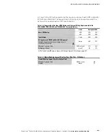
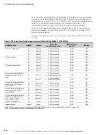
Bypass wiring data is not applicable to IOM configurations.
Содержание Power Xpert Plus 1
Страница 1: ...Power Xpert 9395 UPS and Plus 1 UPS 450 550 kVA Installation and Operation Manual...
Страница 193: ......
Страница 194: ...1642017013 164201701 3...

