Contents
xvi
014–001867
Figures
Figure
1–1
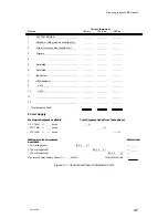
Current and Power Calculation Form
. . . . . . . . . . . . . . . . . . . . . . . . . . . . . .
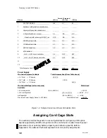
1–2
Sample Current and Power Calculation Form
. . . . . . . . . . . . . . . . . . . . . . .
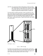
1–3
VME Card Cage
. . . . . . . . . . . . . . . . . . . . . . . . . . . . . . . . . . . . . . . . . . . . . . . . . .
1–4
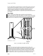
Board Slots in the VME Card Cage
. . . . . . . . . . . . . . . . . . . . . . . . . . . . . . . .
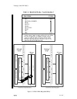
1–5
Board Slot Assignment Map
. . . . . . . . . . . . . . . . . . . . . . . . . . . . . . . . . . . . . . .
2–1
Removing or Installing Jumper Plugs
. . . . . . . . . . . . . . . . . . . . . . . . . . . . . .
2–2
DIP Switches on Printed-Circuit Boards
. . . . . . . . . . . . . . . . . . . . . . . . . . . .
2–3
VAC/16 Board Jumper Locations
. . . . . . . . . . . . . . . . . . . . . . . . . . . . . . . . . . .
2–4
VDA/128 Board Jumper and Switch Locations
. . . . . . . . . . . . . . . . . . . . . .
2–5
VDA/255 Board Jumper Locations
. . . . . . . . . . . . . . . . . . . . . . . . . . . . . . . . .
2–6
VTC Board Jumper Locations
. . . . . . . . . . . . . . . . . . . . . . . . . . . . . . . . . . . . .
2–7
VSC/3 Board Jumper Locations
. . . . . . . . . . . . . . . . . . . . . . . . . . . . . . . . . . . .
2–8
VSC/3i Board Jumper Locations
. . . . . . . . . . . . . . . . . . . . . . . . . . . . . . . . . . .
2–9
VSC/3i Electrical Interface Jumpers
. . . . . . . . . . . . . . . . . . . . . . . . . . . . . . .
2–10 Removing Electrical Interface Selection Jumper Blocks
. . . . . . . . . . . . . .
2–11 VSC/3i Channel Configuration and Configuration Tag
. . . . . . . . . . . . . . .
2–12 VSA Board Jumper Locations
. . . . . . . . . . . . . . . . . . . . . . . . . . . . . . . . . . . . .
2–13 Labeled SCSI Ports
. . . . . . . . . . . . . . . . . . . . . . . . . . . . . . . . . . . . . . . . . . . . . . .
2–14 VSA Board with Daughter Boards Oriented for Differential and
Single-Ended Operation
. . . . . . . . . . . . . . . . . . . . . . . . . . . . . . . . . . . . . . . . . .
2–15 Positioning the Daughter Board for Reattachment
. . . . . . . . . . . . . . . . . .
2–16 VLC Board Switch Locations
. . . . . . . . . . . . . . . . . . . . . . . . . . . . . . . . . . . . . .
2–17 VLCi Board Jumper Locations
. . . . . . . . . . . . . . . . . . . . . . . . . . . . . . . . . . . . .
2–18 VTRC Board Jumper Locations
. . . . . . . . . . . . . . . . . . . . . . . . . . . . . . . . . . . .
2–19 VFC Board Jumper Locations
. . . . . . . . . . . . . . . . . . . . . . . . . . . . . . . . . . . . .
3–1
Typical VME Board Assembly
. . . . . . . . . . . . . . . . . . . . . . . . . . . . . . . . . . . . .
3–2
Rear View of Typical AViiON Computer Systems
. . . . . . . . . . . . . . . . . . . .
3–3
2–Slot Card Cage Layout Showing Guide Rails and
Backplane Connector
. . . . . . . . . . . . . . . . . . . . . . . . . . . . . . . . . . . . . . . . . . . . .
3–4
Air Dams on an AViiON VME Card Cage
. . . . . . . . . . . . . . . . . . . . . . . . . . .
3–5
Old and New EMI/Air Dams
. . . . . . . . . . . . . . . . . . . . . . . . . . . . . . . . . . . . . . .
3–6
EMI/Air Dam Upgrade Kit Installed on an AViiON VME Card Cage
. .
3–7
Mixing Configurations – Boards with Old and New EMI/Air Dams
. . . .
3–8
Releasing Air Dam Screws
. . . . . . . . . . . . . . . . . . . . . . . . . . . . . . . . . . . . . . . .
3–9
Releasing an Option Board
. . . . . . . . . . . . . . . . . . . . . . . . . . . . . . . . . . . . . . . .
3–10 Aligning Board in Card Cage
. . . . . . . . . . . . . . . . . . . . . . . . . . . . . . . . . . . . . .
3–11 Board-Ejector Positions When Installing Board
. . . . . . . . . . . . . . . . . . . . .
3–12 Securing a VME Board in the Card Cage
. . . . . . . . . . . . . . . . . . . . . . . . . . .
3–13 Typical AViiON Unit with VME Backplane Exposed
. . . . . . . . . . . . . . . . .
3–14 Installing or Removing Backplane Terminators
. . . . . . . . . . . . . . . . . . . . .
Содержание AViiON 5000 Series
Страница 2: ......
Страница 6: ......
Страница 12: ...Preface x 014 001867 ...
Страница 86: ...Configuring VME Option Boards 2 52 014 001867 ...
Страница 144: ...Connecting External Devices to VME Option Boards 4 44 014 001867 ...
Страница 150: ...VME Backplane Connector Signals and Power Distribution A 6 014 001867 ...
Страница 196: ...Assigning VME Data Bus and Interrupt Priorities E 10 014 001867 ...
Страница 206: ......
Страница 209: ...Cut here and insert in binder spine pocket Setting Up and Installing VMEbus Options in AViiON Systems 014 001867 03 ...
Страница 210: ...Appendix Title ...

