External Device Connector Pin Assignments
C-8
014–001867
VSC/3i Synchronous Serial Port Connectors
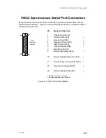
Devices connect to the VSC/3i ports (or channels) through 25–pin female DB25
connectors marked “CH A,” “CH B,” and “CH C.” The signals supported by each
connector on your VSC/3i air dam depend on the interface type you select when
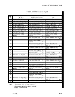
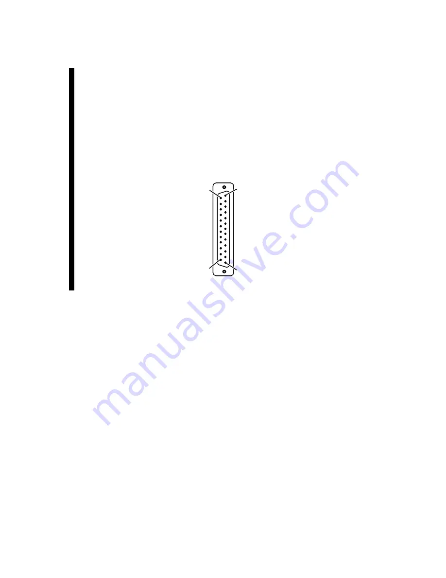
configuring your VSC/3i. Figure C–5 shows the VSC/3i rear panel connector, and
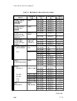
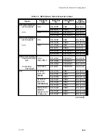
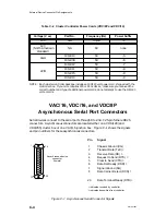
Table C–3 lists the signals and pin numbers for each electrical interface supported
by VSC/3i connectors.
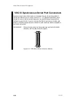
IMPORTANT:
This section provides only the signals leaving the VSC/3i DB25
connector, not the cable connector signals.
1
13
25
14
Figure C–5 VSC/3i Rear Panel Connector (Female)
Содержание AViiON 5000 Series
Страница 2: ......
Страница 6: ......
Страница 12: ...Preface x 014 001867 ...
Страница 86: ...Configuring VME Option Boards 2 52 014 001867 ...
Страница 144: ...Connecting External Devices to VME Option Boards 4 44 014 001867 ...
Страница 150: ...VME Backplane Connector Signals and Power Distribution A 6 014 001867 ...
Страница 196: ...Assigning VME Data Bus and Interrupt Priorities E 10 014 001867 ...
Страница 206: ......
Страница 209: ...Cut here and insert in binder spine pocket Setting Up and Installing VMEbus Options in AViiON Systems 014 001867 03 ...
Страница 210: ...Appendix Title ...


