Preface
vi
014–001867
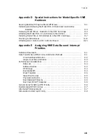
Appendix B
Provides forms for recording the computer’s card cage
configuration, calculating configuration power requirements, and
recording device line information.
Appendix C
Provides Data General part and model numbers for cables that
connect external devices to VME option boards. Describes pin
assignments for option board connector signals.
Appendix D
Provides special instructions for installing and removing
model-specific VME hardware. Describes how to mount VAC/16
junction boxes to an office wall or other surface, and how to attach
the Model 7431 air dam to the board.
Appendix E
Provides guidelines for assigning VME data bus and interrupt
priorities within the Data General AViiON systems environment.
Primarily, the discussion centers around the VME Data Transfer
Bus (DTB) and interrupt priority architecture and the demands
that various types of VME controllers place on bus and system
resources. This information is very technical and intended for
properly trained users only.
Related Documents
This manual refers directly to the documentation listed in this section.
AViiON Systems Documentation
Setting Up, Starting, Expanding, and Maintaining AViiON
Computer Systems:
400, 3000, and 4000 Series (014–002083) and
Setting Up, Starting, Expanding, and Maintaining AViiON
530 and 4600 Series
Computers (014–002091)
Describe how to unpack and connect system components and optional devices.
Explain how to power the computer systems up and down. Describe how to add
or replace mass-storage devices, memory modules, and option boards, and how to
remove and replace the power supply, fan assembly, and system board. Explain
how to use the System Control Monitor (SCM) commands and menus to boot
software, control the system environment, and debug programs.
Testing and Troubleshooting AViiON
Computers: AV/Alert and the AViiON
Diagnostic Tool Set (014–002183)
Describes the diagnostic features available for AViiON
computers. It provides
steps necessary to enable and operate the AV/Alert system, and describes how to
use the DG/UX
–based Service Manager software. The manual also describes
how to use the utilities and tests available with the stand–alone AViiON System
Diagnostics.
VME Options Documentation
The VMEbus Specification (Motorola document number HB212)
Defines the mechanical and electrical specifications, protocols, and terminology
of the VMEbus (Versa Modula Europa bus, or Versa Module European bus).
Содержание AViiON 5000 Series
Страница 2: ......
Страница 6: ......
Страница 12: ...Preface x 014 001867 ...
Страница 86: ...Configuring VME Option Boards 2 52 014 001867 ...
Страница 144: ...Connecting External Devices to VME Option Boards 4 44 014 001867 ...
Страница 150: ...VME Backplane Connector Signals and Power Distribution A 6 014 001867 ...
Страница 196: ...Assigning VME Data Bus and Interrupt Priorities E 10 014 001867 ...
Страница 206: ......
Страница 209: ...Cut here and insert in binder spine pocket Setting Up and Installing VMEbus Options in AViiON Systems 014 001867 03 ...
Страница 210: ...Appendix Title ...


