Preparing to Install VME Options
1-11
014–001867
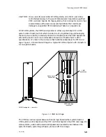
In cases where the arbitrating logic is not physically located within slot 1, its
function is extended via repeaters and/or an interconnecting bus to the first slot of
the VMEbus card cage. This manual refers to the place occupied by the system
board or bus generator/extender, as the case may be, as slot 1. Therefore, it refers to
the first slot in the VME card cage (the slot closest to slot 1) as slot 2. Slot 2 in the
card cage is your first VME option board slot.
Slot Priority
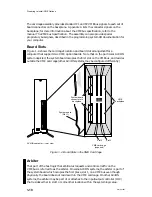
Arbitration logic on the system board permits access to the VMEbus in a daisy chain
arrangement. Requests to use the bus travel from requesting controller boards via
the VME bus through intervening controllers to the arbiter, located either in slot 1
or in the system logic chassis, as the case may be. The arbiter processes the
requests and grants the bus to the requestor having the highest priority.
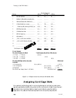
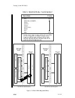
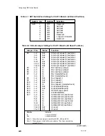
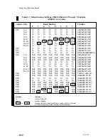
Table 1–2 lists the VME option boards supplied and supported by Data General in
the order of suggested slot priority for 2–slot systems. Assign your boards to the card
cage slots beginning with any VTC board in slot 2 (VMEbus slot 1 is used by the
system and is unavailable to the user) and ending with a VSA board in the last
occupied slot. If your planned configuration includes more than one VME option of
the same type –– for example, a VSC/3 and a VSC/3i (both synchronous controllers),
or a VDA/128 and a VAC/16 (both asynchronous controllers) –– assign the first board
(0) to the position of highest slot priority (slot 2). Chapter 2 describes how to
identify and specify board numbers.
NOTE:
The recommended slot priority shown in Table 1–2 is for 2–slot systems
and assumes all VME boards are jumpered to the default interrupt and bus
request values listed in Chapter 2. For information about assigning
VMEbus priority levels on systems with more than two slots, refer to
Appendix E of this manual and to The VMEbus Specification manual. Also
refer to the manual on programming system I/O for your computer.
Figure 1–5 contains two slot layouts for a 2-slot computer card cage. The first is a
sample configuration; use the second illustration to record your configuration for
future reference. When you assign a board to a slot, write the board’s name into the
appropriate slot of the illustration to the right. If the slot is empty, write the word
“empty” in the slot. Make certain you enter any existing boards along with the new
boards in the planned configuration. Appendix B contains extra illustrations that
you can copy.
Assign slots beginning with slot 2. If slot 2 is empty and slot 3 contains a VME
board, you must install jumpers on the backplane; you should avoid this task if
possible. Note any need for backplane jumpers, since you will need this information
to finish configuring your system.
Once you have assigned the card cage slot for each VME option board, read the next
section on avoiding electrostatic discharge damage before you begin to physically
handle the boards or any other system components.
Содержание AViiON 5000 Series
Страница 2: ......
Страница 6: ......
Страница 12: ...Preface x 014 001867 ...
Страница 86: ...Configuring VME Option Boards 2 52 014 001867 ...
Страница 144: ...Connecting External Devices to VME Option Boards 4 44 014 001867 ...
Страница 150: ...VME Backplane Connector Signals and Power Distribution A 6 014 001867 ...
Страница 196: ...Assigning VME Data Bus and Interrupt Priorities E 10 014 001867 ...
Страница 206: ......
Страница 209: ...Cut here and insert in binder spine pocket Setting Up and Installing VMEbus Options in AViiON Systems 014 001867 03 ...
Страница 210: ...Appendix Title ...


