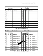
Connecting External Devices to VME Option Boards
4-4
014–001867
Connecting a Junction Box to a Model 7411–KA VAC/16
Controller
Each Model 7411–KA VAC/16 controller board in your computer extends its signals
to two 8-port junction boxes through a 5-ft cable with 68-pin connectors at either
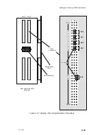
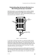
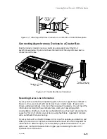
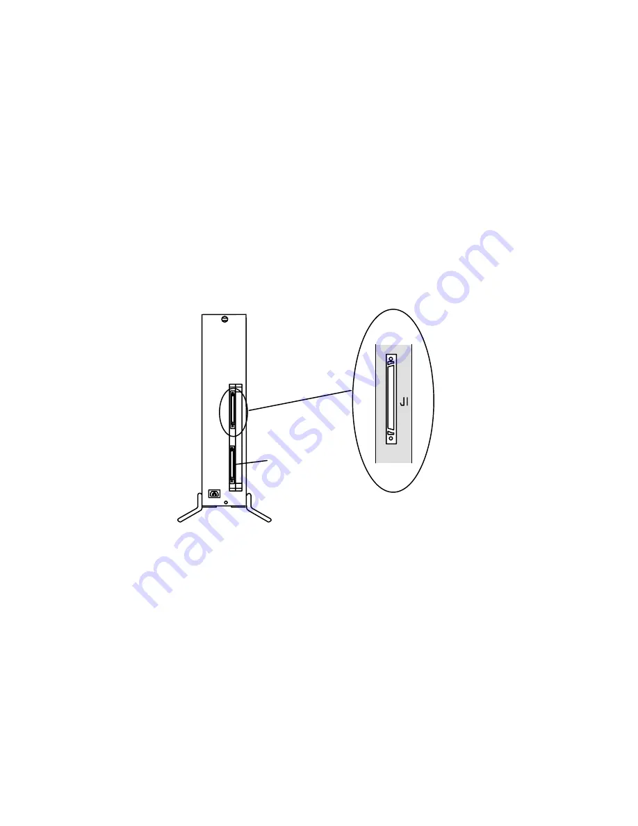
end. Figure 4–2 shows the location of the J1 and J2 connectors on the VAC/16
board. Each connector supports an 8-port junction box.
NOTE:
This chapter describes the Model 7411–KA VAC/16 assembly. Its
counterpart Model 7411–K VAC/16 assembly uses nonstandard hardware
(heavy gauge air dam without ejector handles, ribbon rather than hose
cable between controller and J-box, and 64- rather than 68-pin connectors).
To attach Model 7411–K junction boxes and controller boards, refer to
Appendix D for special instructions.
VAC/16 to J-box connector (J1)
(female)
AViiON computer — rear view
J2 connector
Figure 4–2 VAC/16 Controller Connectors
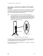
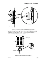
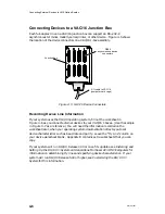
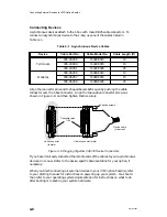
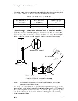
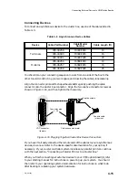
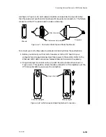
To connect a J-box to your controller, align the connector pins and D-shaped bevels
on the cable, controller, and junction box connectors before gently pushing the
connectors together as shown in Figures 4–3 and 4–4.
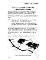
Plug each 68-pin cable connector into the proper J1 or J2 connector on the VAC/16
board, as shown in Figure 4–3.
Содержание AViiON 5000 Series
Страница 2: ......
Страница 6: ......
Страница 12: ...Preface x 014 001867 ...
Страница 86: ...Configuring VME Option Boards 2 52 014 001867 ...
Страница 144: ...Connecting External Devices to VME Option Boards 4 44 014 001867 ...
Страница 150: ...VME Backplane Connector Signals and Power Distribution A 6 014 001867 ...
Страница 196: ...Assigning VME Data Bus and Interrupt Priorities E 10 014 001867 ...
Страница 206: ......
Страница 209: ...Cut here and insert in binder spine pocket Setting Up and Installing VMEbus Options in AViiON Systems 014 001867 03 ...
Страница 210: ...Appendix Title ...

