Installing and Removing VME Option Boards
3-10
014–001867
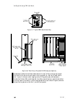
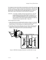
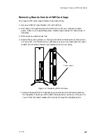
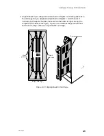
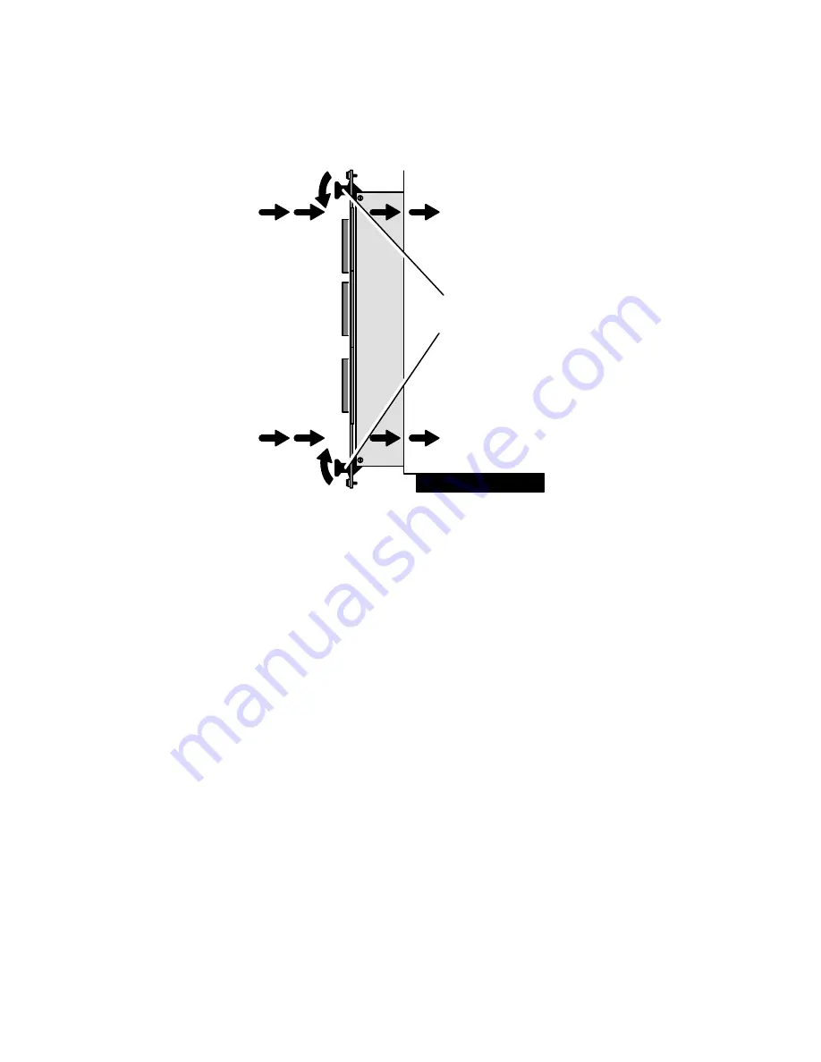
5. Engage the board carefully in the rails of the card cage. Push the board
straight in one-half of the way, using the handles as shown in Figure 3–11.
Board
ejector
handles
Computer chassis — side view
Figure 3–11 Board-Ejector Positions When Installing Board
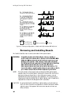
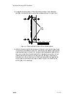
6. With the board one-half of the distance into the slot, verify that the board rests
in both the top and bottom guide rails. With the top and bottom board ejectors
positioned as shown in Figure 3–11, carefully slide the board straight into the
slot until you feel the connectors seat with the backplane connectors. Do not
push the board from side to side or otherwise risk bending or breaking the
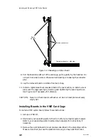
connector pins. The air dam on your VME board should be flush against the
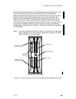
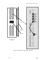
securing bar when the board is properly seated. Figure 3–12 identifies the
securing bar in the card cage.
Содержание AViiON 5000 Series
Страница 2: ......
Страница 6: ......
Страница 12: ...Preface x 014 001867 ...
Страница 86: ...Configuring VME Option Boards 2 52 014 001867 ...
Страница 144: ...Connecting External Devices to VME Option Boards 4 44 014 001867 ...
Страница 150: ...VME Backplane Connector Signals and Power Distribution A 6 014 001867 ...
Страница 196: ...Assigning VME Data Bus and Interrupt Priorities E 10 014 001867 ...
Страница 206: ......
Страница 209: ...Cut here and insert in binder spine pocket Setting Up and Installing VMEbus Options in AViiON Systems 014 001867 03 ...
Страница 210: ...Appendix Title ...

